Heat exchanger

a heat exchanger and heat exchanger technology, applied in indirect heat exchangers, lighting and heating apparatus, stationary conduit assemblies, etc., can solve the problems of increased temperature distribution difference of discharged air, unstable air-conditioning system, passengers may feel unfavorable, etc., to improve heat exchange efficiency, reduce the effect of size and uniform surface temperature distribution

Active Publication Date: 2009-04-28
HANON SYST
View PDF18 Cites 12 Cited by
  • Summary
  • Abstract
  • Description
  • Claims
  • Application Information

AI Technical Summary

Benefits of technology

[0024]Accordingly, to solve the above disadvantages of the prior arts, it is an object of the present invention to provide a heat exchanger, in which inlet and outlet side heat exchange parts are fluidically communicated with each other and have the same refrigerant flowing direction by fluidically communicating pairs of cups with each other which are located at a predetermined area of the center of the heat exchanger, thereby being easily reduced in size, providing uniform surface temperature distribution and improving heat exchange efficiency by reducing the preponderance and the pressure drop rate of refrigerant, and inlet and outlet pipes being easily arranged forward, and by mutually complementarily exchanging heat between the inlet and outlet side heat exchange parts.

Problems solved by technology

Therefore, the air passing between all of the tubes 10 does not exchange heat uniformly, and so, the temperature distribution difference of the discharged air becomes more severe.
In addition, a problem of icing may occur on the surface of the evaporator and the air-conditioner system becomes unstable in the overcooled section.
Additionally, in the overheated section, since the discharged air is not normally cooled and dehumidified, temperature-increased damp air is induced into a car, and thereby, passengers may feel uneasiness.
Furthermore, the conventional evaporator has another problem in that it is difficult to arrange the inlet pipe 4 and the outlet pipe forward since they are all arranged at one side of the evaporator 1.

Method used


Image

  • Heat exchanger
  • Heat exchanger
  • Heat exchanger

Examples


first embodiment

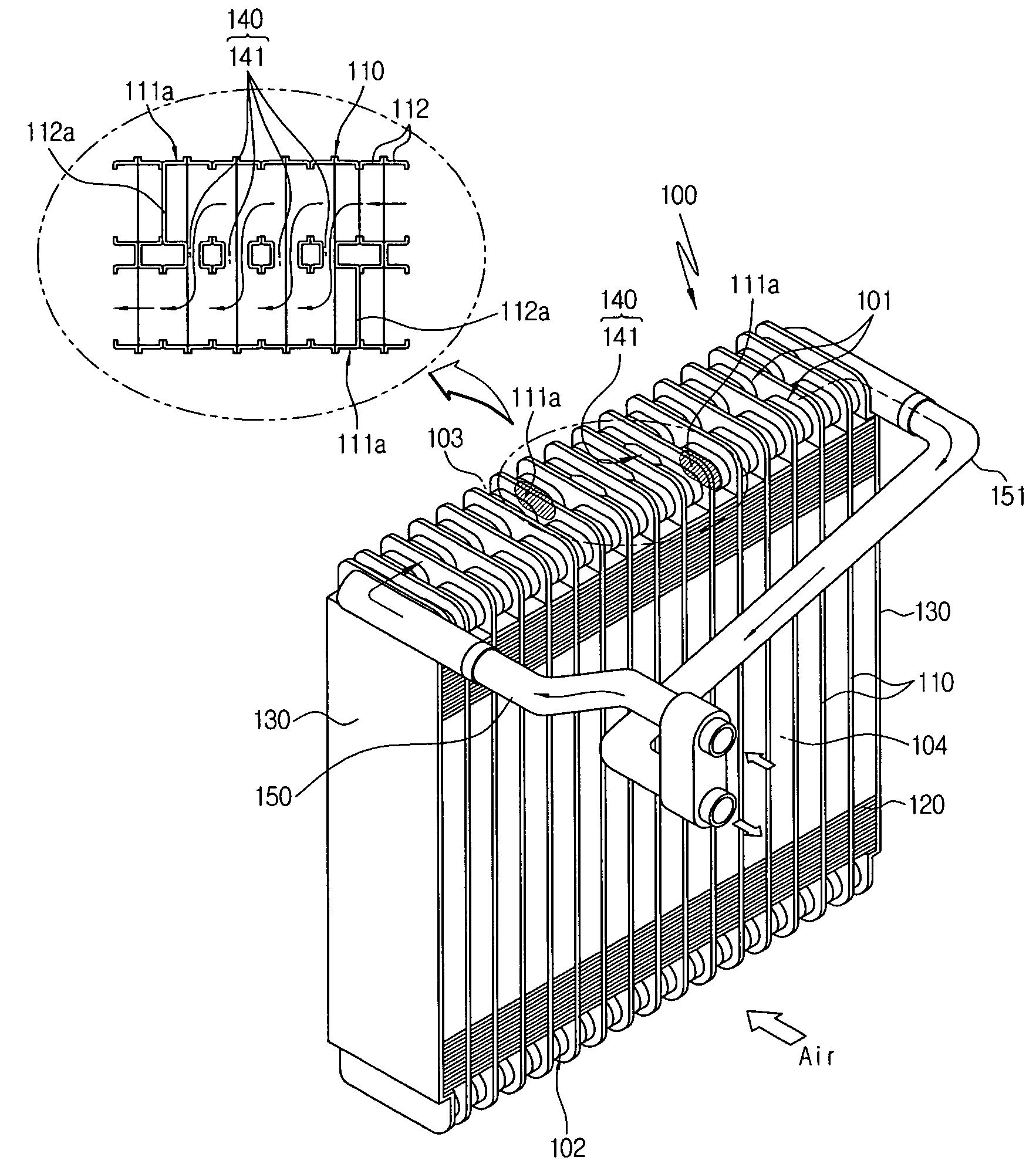
[0086]In the first embodiment, the flow of refrigerant may be lopsided to the end portion by inertia since the outlet pipe 151 is located at the end portion of the heat exchanger 100. That is, refrigerant flows very rapidly in the outlet side heat exchange part 104 since it is in a gas state therein. Furthermore, since the outlet side heat exchange part 104 is very sensitive to refrigerant flowing noise, if refrigerant is lopsided in the outlet side heat exchange part 104, the refrigerant flowing noise may be generated, and ununiform refrigerant distribution and uneven temperature may be caused.

fourth embodiment

[0087]Therefore, in the fourth embodiment, the outlet pipe 151 is mounted at the center of the fourth heat exchange zone 108 which is the last heat exchange zone of the outlet side heat exchange part 104 so that the lopsidedness of refrigerant at the outlet side heat exchange part 104 which is more overheated than the inlet side heat exchange part 103 is prevented and the refrigerant distribution becomes uniform, whereby the refrigerant flowing noise is reduced and also the temperature becomes uniform by reducing the lopsidedness of refrigerant toward the outlet pipe 151 due to inertia.

[0088]As described above, the inlet and outlet side heat exchange parts are fluidically communicated with each other and have the same refrigerant flowing direction by communicating a pair of the cups with each other which are located at the predetermined area of the center of the heat exchanger, whereby the heat exchanger can be reduced in size by reducing the preponderance and the pressure drop rate...


PUM


Abstract

The present invention relates to a heat exchanger, in which inlet and outlet side heat exchange parts are communicated with each other and have the same refrigerant flowing direction by communicating pairs of cups with each other which are located at a predetermined area of the center of the heat exchanger, thereby being easily reduced in size, providing uniform surface temperature distribution and improving heat exchange efficiency by reducing the preponderance and the pressure drop rate of refrigerant and inlet and outlet pipes being easily arranged forward.

Description

[0001]This application claims priority from Korean Patent Application No: 2005-6303 filed Jan. 24, 2005, Korean Patent Application No: 2005-6316 filed Jan. 24, 2005 and Korean Patent Application No: 2006-842 filed Jan. 4, 2006, each of which is incorporated by reference in its entirety.BACKGROUND OF THE INVENTION[0002]1. Field of the Invention[0003]The present invention relates to a heat exchanger, and more particularly, to a heat exchanger, in which inlet and outlet side heat exchange parts are fluidically communicated with each other and have the same refrigerant flowing direction by fluidically intercommunicating pairs of cups which are located at a predetermined area of the center of the heat exchanger, thereby being easily reduced in size, providing uniform surface temperature distribution of the heat exchanger and improving heat exchange efficiency by reducing the preponderance and the pressure drop rate of refrigerant and inlet and outlet pipes being easily arranged forward.[...

Claims


Application Information

Patent Timeline
Patent Type & Authority Patents(United States)
IPC IPC(8): F28D1/02F28D7/06F28F9/02
CPCF28D1/0333F28F9/0202F28F9/0282F28F9/262
Inventor OH, KWANGHEONLIM, HONGYOUNG
Owner HANON SYST
Why Eureka
Try Eureka