Inflatable restraint assembly for vehicles

a technology for occupants and restraints, applied in child seats, vehicle components, vehicle arrangements, etc., can solve the problems of hyperextension and/or hyperflexion type injuries, occupants often suffer damage, and conventional airbags, etc., to reduce injury and reduce acceleration. the effect of declaration for

Inactive Publication Date: 2009-04-28
ZC HLDG
View PDF22 Cites 13 Cited by
  • Summary
  • Abstract
  • Description
  • Claims
  • Application Information

AI Technical Summary

Benefits of technology

[0011]Accordingly, there remains a need in this art for a restraint assembly which is designed and structured to more actively intercept at least the head and neck motion of an occupant riding in a motor vehicle undergoing a collision or other impact. More specifically, there is a need for an inflatable restraint assembly which attempts to actively oppose the forces of impact between a passenger and an air bag, sufficiently to diffuse such forces by applying an equal and opposite force, while buffering the passenger's impact, and thereby, reducing dynamically and actively, the range of motion of the head, neck and torso, caused by the impact as well as acceleration-declaration. Any such improved restraint assembly developed would preferably also utilize at least two, oppositely disposed and pressure sensing inflatable members, each having a plurality of chambers, and further, through the application of microcomputer-microprocessor technology, initiate a positive gradient increase in pressures to some, but not all chambers of the pressure sensing inflatable member, for the specific purpose of slowing the acceleration—declaration forces at work on an occupant's body, while applying an equal and opposite force to the force of impact of the occupant's body with the other(s) of the inflatable members. Any such improved restraint system should further include a plurality of inflatable restraint devices or bags strategically located at various points throughout the passenger compartment, including but not necessarily limited to the ceiling, door post and seat belts, so as to provide as much surrounding or “global” protection as possible, with the goal being to significantly reduce injury by a reduction of the forces exerted on the occupant's body during impact type accidents. In addition, any such improved restraint assembly developed should also overcome the long existing problems of known restraint systems through the ability to actively oppose impact forces “intelligently” through a series of dynamic pressure measurements conducted in response to the acceleration—deceleration to the various portions of the passenger's body as the body impacts substantially oppositely disposed, but cooperatively positioned, inflatable members.
[0019]While the inflatable restraint assembly of the present invention contemplates the use of at least one inflatable member having the aforementioned impact absorption zone and impact resistance zone, maximum protection to the one or more occupants may best be provided through the use of at least two of the aforementioned inflatable members, disposed in substantially opposing relation to one another. When such two inflatable members are cooperatively positioned they each act as “interceptors” for the purpose of reducing the normal, relatively excessive to-and-fro motion to lesser oscillations by allowing the force of impact of the occupant onto a first of the inflatable members to be at least partially absorbed, but at the same time, resisted by actively regulating the pressure within the first inflatable member. At the same time, the pressure within the inflatable member needed to respond to the degree of the force of impact of the occupant thereon is determined. This information is then relayed, through cooperative workings of the sensing assembly with the processor, to communicate the expected and / or summate force of impact of the occupant onto the second or intercepting one of the cooperatively positioned two inflatable members. The relayed information then allows the pressure within the second of the inflatable members to be further regulated or varied to again absorb the force of impact onto the second inflatable member. As will be explained in greater detail hereinafter, the processor and sensor assembly are cooperatively structured and operationally functional so as to arrive at a summation of the pressure within each of the inflatable members and vary the total pressure so as to accomplish absorption of the force of impact of the occupant by means of at least partial deflation of the impact absorption zone while maintaining an opposing resistance force in the impact resistance zone of each inflatable member. The summation of the pressure within any of the inflatable members, should not exceed the force of impact of the occupant onto the inflatable member, so as to not result in a forcible rebounding of the occupant, which would add to the acceleration / deceleration or to-and-fro motion of the occupant.
[0022]In one aspect of the invention, sensors provide information to a processor which, relying on various algorithms, look-up tables, and the like, intelligently instructs responses to a system of inflatable restraints. Such responses include the selection, timing and infilling pressures of inflatable members. As modem processing times are generally measured in microseconds, and the forces of injury generally act in milliseconds, the use of such high-speed intelligent analysis and response provides a time advantage over the forces of injury.
[0024]The various preferred embodiments of the present invention as described above, as well as additional preferred embodiments to be described hereinafter, are intended to overcome many of the disadvantages and problems associated with conventional restraint systems. As with the preferred embodiments described above, the preferred embodiments described hereinafter are specifically directed to better protect occupants in a motor vehicle.
[0027]Further, the restraint assembly of the present invention accomplishes strategic movement restriction of the spinal column, head and neck to reduce the forces of deceleration, linear and angular momentum, flexion, extension and rotation through the use of a plurality of inflatable members and / or a restraint harness. More specifically, in certain strategic locations within a vehicle, one or more of the inflatable members are deployed away from the body towards, for example the steering wheel. In this particular embodiment, one or more deployed inflatable members meet and confront a cooperatively disposed and structured inflatable member, issuing from the vehicle interior, such as from the steering wheel, or side posts or doors, impacting air bag to air bag. Also and importantly, the ventral space disposed in front of the body is reduced. This therefore, serves to fill the emptiness or void into which the body has a tendency to move during the type of impacts or emergency conditions described herein.
[0028]Other structural features of the additional preferred embodiments of the present invention include adjustable belt segments of a restraining harness, such as a horizontal chest belt segment thereof. The chest belt segment is operatively disposed in a substantially horizontal orientation from underarm to underarm in overlying, protective relation to the upper chest of the occupant. In addition, yet another structural modification of this preferred embodiment may include an additional or supplementary inflatable member mounted within a receptacle in the chest belt segment or other portions of the harness. When deployed the supplementary or additional inflatable member extends upwardly, underneath the chin area and is further dimensioned and configured to extend laterally about opposite sides of the neck. Therefore, there is a reduction in the forces of neck flexion and, perhaps, lateral flexion. The chest belt of the restraining harness segment therefore significantly reduces the lever arm action of the spine on the low back, almost to the point of elimination. Accordingly, since angular momentum is proportional to the length of the lever arm which sets the head in motion, the fulcrum of the lever arm is displaced from the low back to the base of the neck (C7 through T1 vertebrae). This makes the lever arm of the spinal column shorter. A shorter “lever arm” means smaller angular momentums which are translated into reduced forces of injury or possibly preventable injuries. This concept of restraint permits the possibility for using smaller airbags, thereby reducing costs. The horizontal restraint houses an under chin or submental airbag which restricts forward motion of the head and neck, while cushioning along with a headrest airbag for the posterior neck.

Problems solved by technology

As a result, the occupant frequently suffers damage upon impact with the conventional air bag and quite frequently suffers hyperextension and / or hyperflexion type injuries, due to a forceful forward and backward acceleration of the head on the neck and / or the body torso upon the lower back and hip.

Method used


Image

  • Inflatable restraint assembly for vehicles
  • Inflatable restraint assembly for vehicles
  • Inflatable restraint assembly for vehicles

Examples


Embodiment Construction

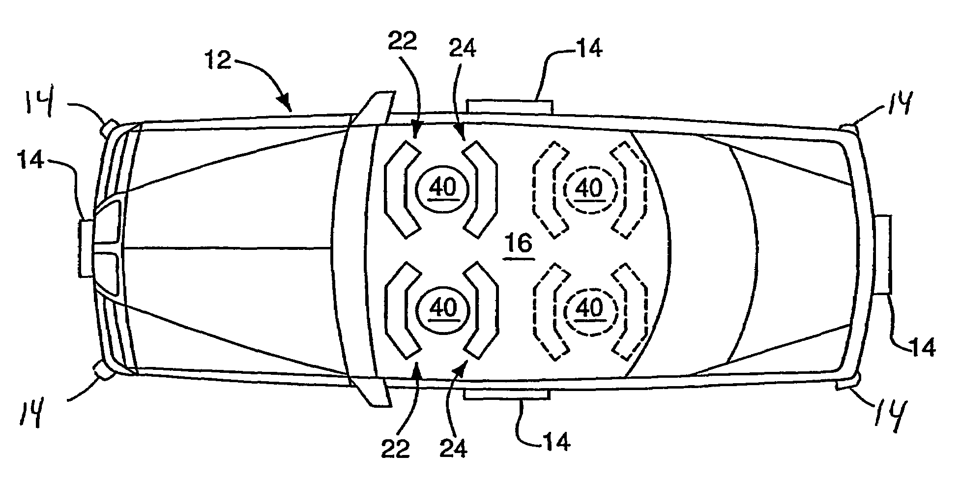
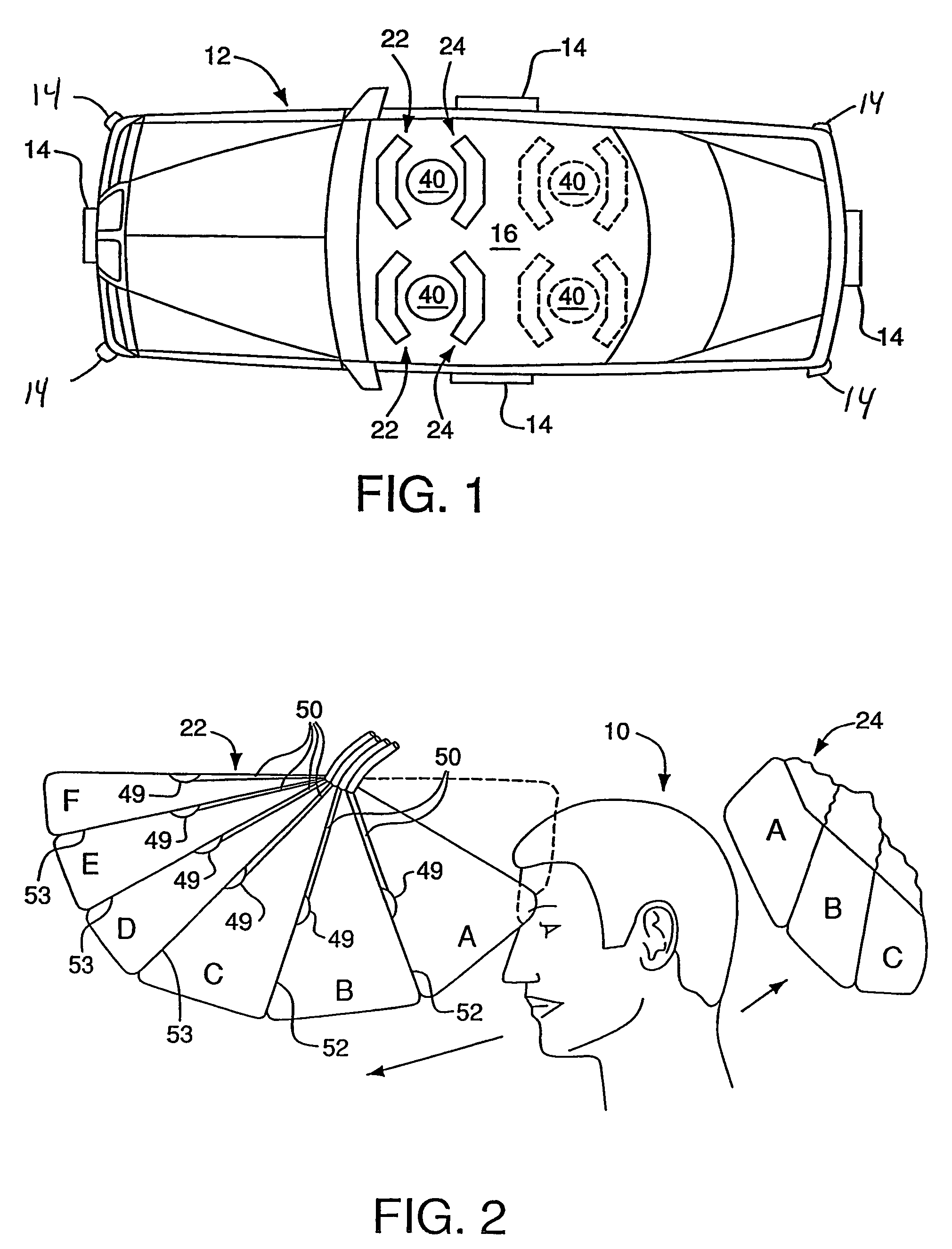
[0090]As shown in the accompanying drawings, the present invention relates to a restraint assembly designed primarily, but not exclusively, to protect occupants, generally indicated as 10, within a motor vehicle, generally indicated at 12.

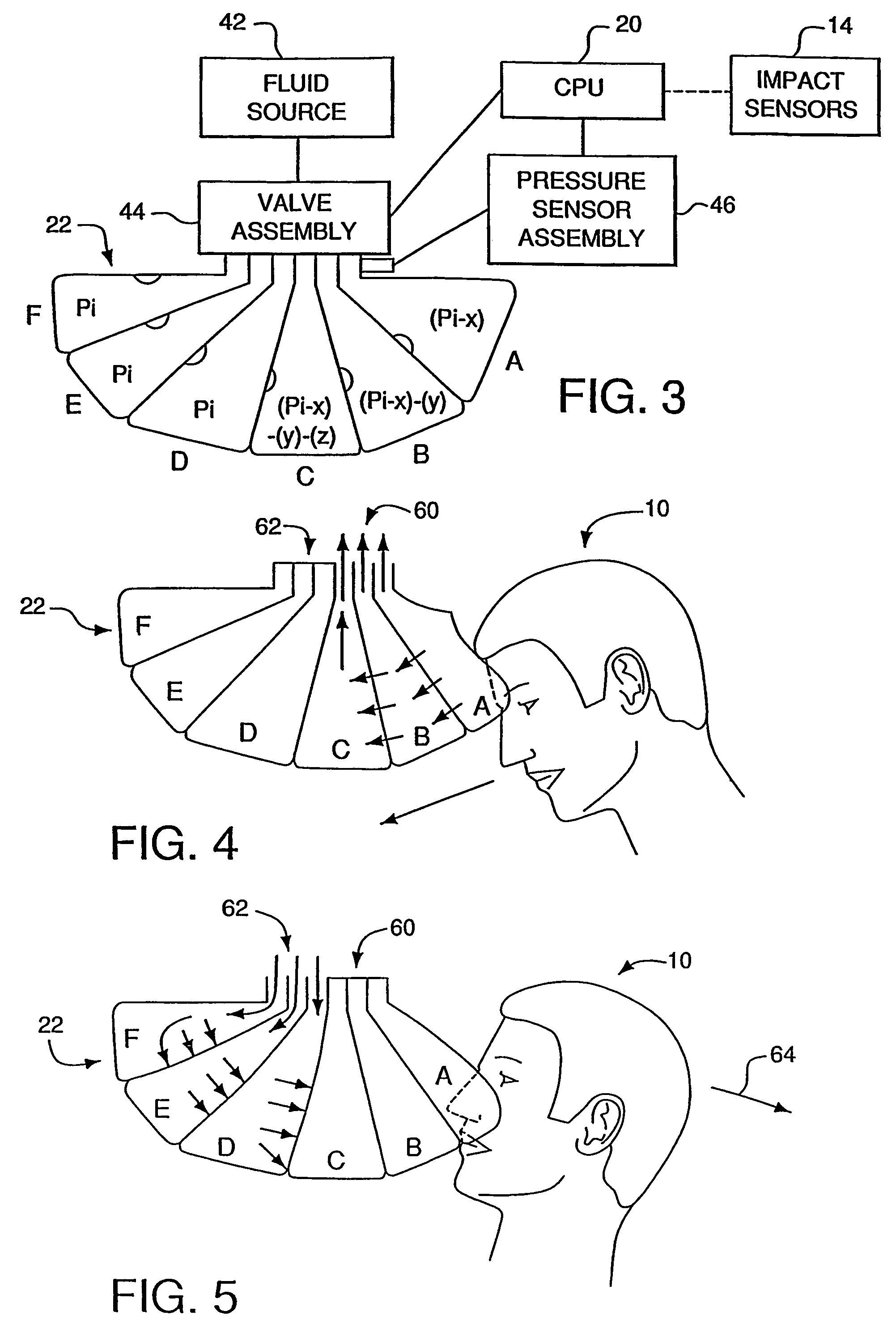
[0091]More specifically, and as shown in FIG. 1, the vehicle 12 is equipped with a plurality of impact sensors, as at 14, located at various positions on the vehicle, so as to sense the occurrence of an impact of sufficient degree to possibly cause harm to occupants within the passenger compartment 16 of the vehicle 12. The location of the impact sensors 14 in FIG. 1 is meant to be representative only of a plurality of locations where such impact sensors 14 could be positioned, the knowledge of which is possessed by persons of skill in the art relating to air bag deployment. In addition, and as shown in FIG. 3, the impact sensors 14 are operably connected and / or coupled to a computer processor, such as a micro-processing chip or other central proce...


PUM


Abstract

A plurality of inflatable members (136, 140, 142, 156′) are mounted at a plurality of strategic locations relative to a vehicle occupant. The occupant is restrained by a harness including a lap belt segment (124), a chest belt segment (126) and a diagonal belt segment (128). Upon the vehicle being impacted, a central processor automatically inflates the inflatable members (136, 140, 142, 156′). The processor is connected to valve assemblies that regulate air flow both into and out of the inflatable members (136, 140, 142, 156′), and is further responsive to a pressure sensor assembly, so as to actively regulate pressure within the inflatable members.

Description

[0001]This application claims the benefit of Int'l. Application No. PCT / US03 / 003339, filed Feb. 3, 2003, and is incorporated herein by reference, and is a continuation-in-part of U.S. patent application Ser. No. 09 / 825,036, filed Apr. 3, 2001, now U.S. Pat. No. 6,513,829, which is a continuation-in-part of U.S. patent application Ser. No. 09 / 470,922, filed Dec. 23, 1999, now U.S. Pat. No. 6,209,908, each of which is hereby incorporated herein by reference in its entirety.FIELD OF THE INVENTION[0002]This invention relates to an inflatable restraint system primarily designed for use within a motor vehicle to protect occupants when the vehicle is involved in an accident, and specifically, a collision or other type of crash or impact. The inflatable restraint system comprises a central processing unit or other processor operatively connected to both a sensor assembly and a variable valve assembly in order to initially inflate and actively regulate pressure within a first and second plur...

Claims


Application Information

Patent Timeline
Patent Type & Authority Patents(United States)
IPC IPC(8): B60R21/16B60N2/28B60R21/00B60R21/01B60R21/015B60R21/18B60R21/20B60R21/203B60R21/207B60R21/231B60R21/233B60R21/26B60R21/276
CPCB60N2/286B60N2/2884B60R21/18B60R21/2072B60R21/231B60R21/232B60R21/233B60R21/01516B60R21/01508B60R21/203B60R2021/0004B60R2021/0006B60R2021/0011B60R2021/01211B60R2021/2074B60R2021/23107B60R2021/23324B60R2021/26094B60R2021/2765
Inventor ZUMPANO, BERNARD J.
Owner ZC HLDG
Why Eureka
Try Eureka