Drug infusion device

a technology of infusion device and drug, which is applied in the direction of automatic syringes, process and machine control, instruments, etc., can solve the problems of limiting the portability of infusion device for ambulatory patients in hospitals or at home, demanding very tight manufacturing tolerances, and being too expensive to be used as disposable products, etc., to achieve stable and constant infusion device

Active Publication Date: 2009-04-28
UNITED THERAPEUTICS CORP
View PDF21 Cites 113 Cited by
  • Summary
  • Abstract
  • Description
  • Claims
  • Application Information

AI Technical Summary

Benefits of technology

[0015]It is an object of this invention to produce a drug delivery system wherein said system overcomes the heat and pressure sensitivities of the prior art gas-driven systems, thereby providing a stable and constant infusion device.
[0016]A further object of this invention is to provide an infusion device wherein the driving force does not directly determine the infusion rate, so that friction effects are negligible and manufacturing tolerances are less critical.
[0017]Another object of this invention is to produce a simple and disposable means of infusion in which the infusion rate for the drugs can be controlled by an electric current.

Problems solved by technology

However, all these systems require large, complicated supports along with electronic or mechanical pumps which restrict their portability for ambulatory patients in hospitals or at home.
In these devices, torque is translated to drug pressure and, as a result, the mechanism is very sensitive to friction and thus demands very tight manufacturing tolerances.
Moreover, whereas the lead screw method is very accurate and reliable, it is too expensive to be used as a disposable product.
Accordingly, the products of this nature suffer from the disadvantage that they require filling “in the field” and the manufacturers are required to provide a maintenance infrastructure.
Given the medical importance of the devices, this maintenance becomes a critical issue.
The central problem with these gas-driven devices is that they all employ a gas-filled chamber in order to drive the drug infusion.
As gases are very susceptible to changes in ambient temperature and air pressure, the danger of employing this principle is that a significant and undesirable change in the flow-rate will occur as such temperature or pressure changes occur.
For example, a loss of pressure in an airplane could result in a sudden bolus being delivered at an inappropriate time.
Similarly, a drop in temperature could result in the drug infusion stopping.
For these reasons, despite massive development efforts, these products have faced considerable commercial obstacles to implementation.
Nonetheless, this issue of heat and pressure sensitivity is an inherent disadvantage inhibiting the commercialization of these products.

Method used


Image

  • Drug infusion device
  • Drug infusion device
  • Drug infusion device

Examples


Embodiment Construction

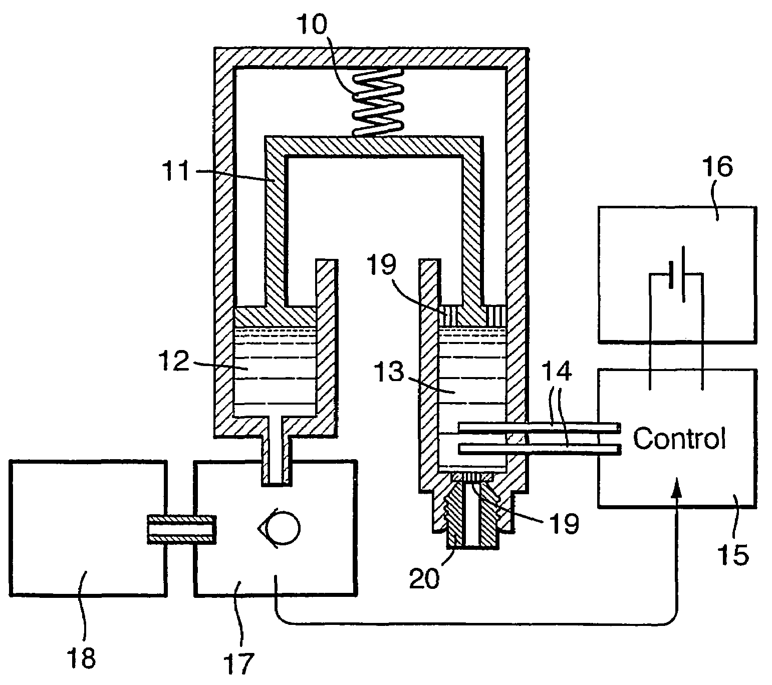
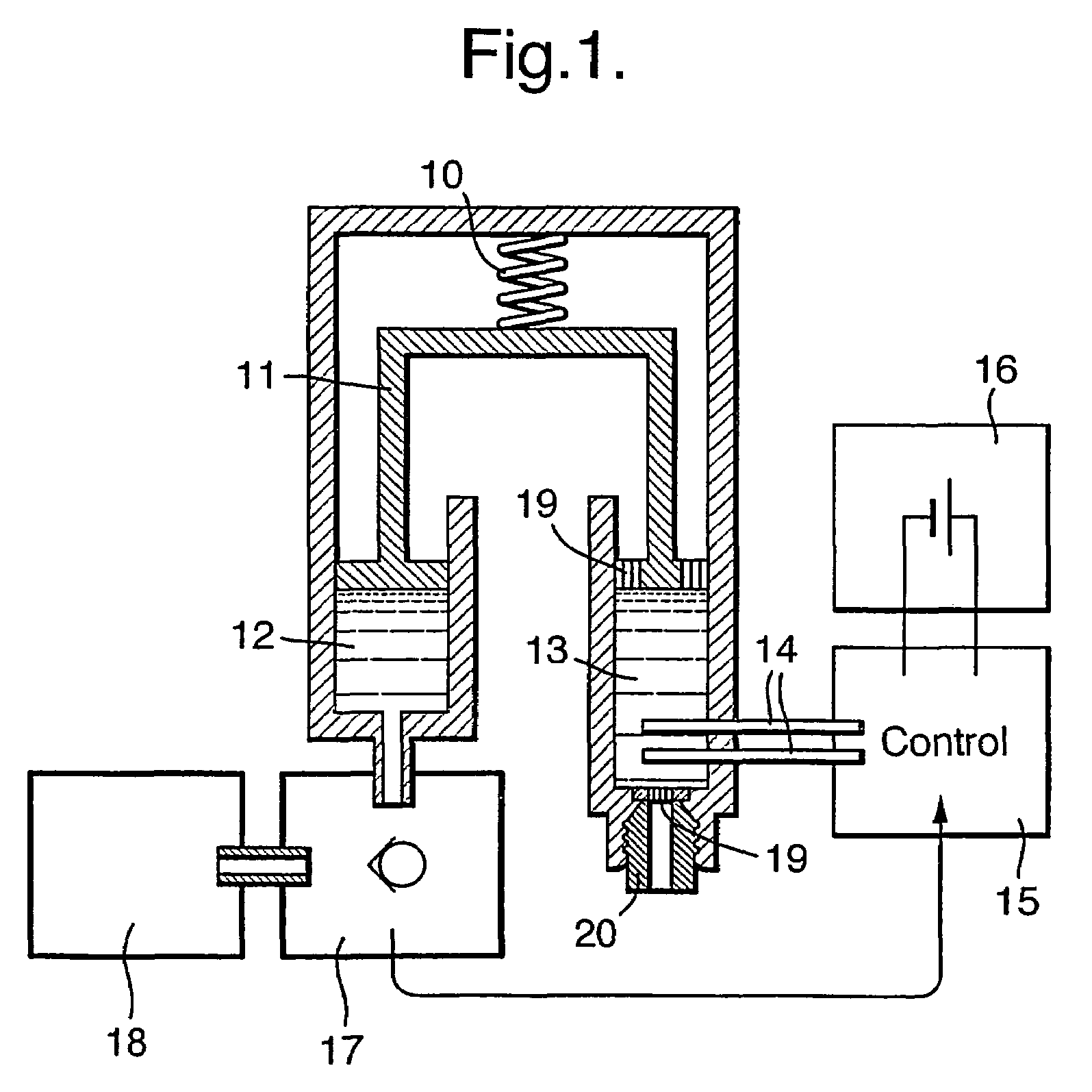
[0043]FIG. 1 shows a schematic representation of the main functional elements of a disposable infusion device. Said device can be either attached to a strap or belt, or adhered to the body. In a preferred embodiment, the pressure-generation means driving the infusion is provided by a spring 10 such as a stainless steel “coil spring”. Said spring serves to provide a source of force along the axis 11. Advantageously, the tolerance of this spring is not a critical factor in the design of the infusion device; it is sufficient that the force is provided in excess, albeit limited such that the pressure applied to the drug remains below the values that could be harmful to the body and / or are limited by regulations and standards. Said axis 11 in turn applies force to the contents of two chambers: the drug reservoir chamber 12 and the control chamber 13. In a preferred embodiment, the control chamber 13 contains an electrolysis solution (composed of water and salt) together with electrodes 1...


PUM


Abstract

The invention provides a drug delivery infusion device comprising an injection means (18) in fluid connection with a drug reservoir chamber (12) and pressure-generation means (10) coupled to both the drug reservoir (12) and to a liquid-filled control chamber (13), wherein the coupling is such that the liquid-filled control chamber (13) serves to constrain the motion of the pressure-generation means (10), thereby controlling the drug infusion rate, wherein the liquid-filled control chamber (13) is associated with means for controlled depletion of the liquid therein whereby depletion of the volume of liquid in the control chamber enables the pressure-generation means to drive the drug in the reservoir chamber therefrom for infusion thereof.

Description

CROSS REFERENCE TO RELATED APPLICATIONS[0001]This application is the U.S. national stage application of International Application PCT / IL2004 / 000099, filed Feb. 2, 2004, which was published on Aug. 12, 2004, as International Publication WO2004 / 067066 in the English language. The International Application claims priority of Israel Patent Application 154,243, filed Feb. 2, 2003.CROSS-REFERENCE TO RELATED APPLICATIONS[0002]Not applicable.STATEMENT REGARDING FEDERALLY SPONSORED RESEARCH OR DEVELOPMENT[0003]Not applicable.THE NAMES OF THE PARTIES TO A JOINT RESEARCH AGREEMENT[0004]Not applicable.INCORPORATION-BY-REFERENCE OF MATERIAL SUBMITTED ON A COMPACT DISC[0005]Not applicable.BACKGROUND OF THE INVENTION[0006](1) Field of the Invention[0007]This invention relates to a system for the administration of drugs and / or biologically active materials by infusion. More particularly, this invention relates to a delivery device in which the gradual reduction of a liquid volume in a control chamb...

Claims


Application Information

Patent Timeline
Patent Type & Authority Patents(United States)
IPC IPC(8): A61M5/20A61M5/142A61M5/145A61M5/168
CPCA61M5/1454A61M5/14248A61M5/16804A61M2005/14204A61M2005/14513
Inventor GENOSAR, AMIR
Owner UNITED THERAPEUTICS CORP
Why Eureka
Try Eureka