Adjustable rear pistol sight and sight mounting and adjustment method

a rear pistol and adjustment method technology, applied in the field of adjustment of optical devices, can solve the problems of not many adjustment options, inability to adjust finely, and relatively fragile target sights, and achieve the effect of precise and convenient sight adjustmen

Inactive Publication Date: 2009-05-05
KENG +1
View PDF13 Cites 43 Cited by
  • Summary
  • Abstract
  • Description
  • Claims
  • Application Information

AI Technical Summary

Benefits of technology

[0015]Accordingly, it is a primary object of the present invention to overcome the above mentioned difficulties by providing a m...

Problems solved by technology

While the combat sights of the prior art do provide a smooth and snag-free draw, a clear sight picture and rugged service, they do not provide the adjustability many have come to enjoy when using target pistols equipped with adjustable target sights.
Adjustments for windage have required the shooter to strike the side of the sight wit...

Method used


Image

  • Adjustable rear pistol sight and sight mounting and adjustment method
  • Adjustable rear pistol sight and sight mounting and adjustment method
  • Adjustable rear pistol sight and sight mounting and adjustment method

Examples


first embodiment

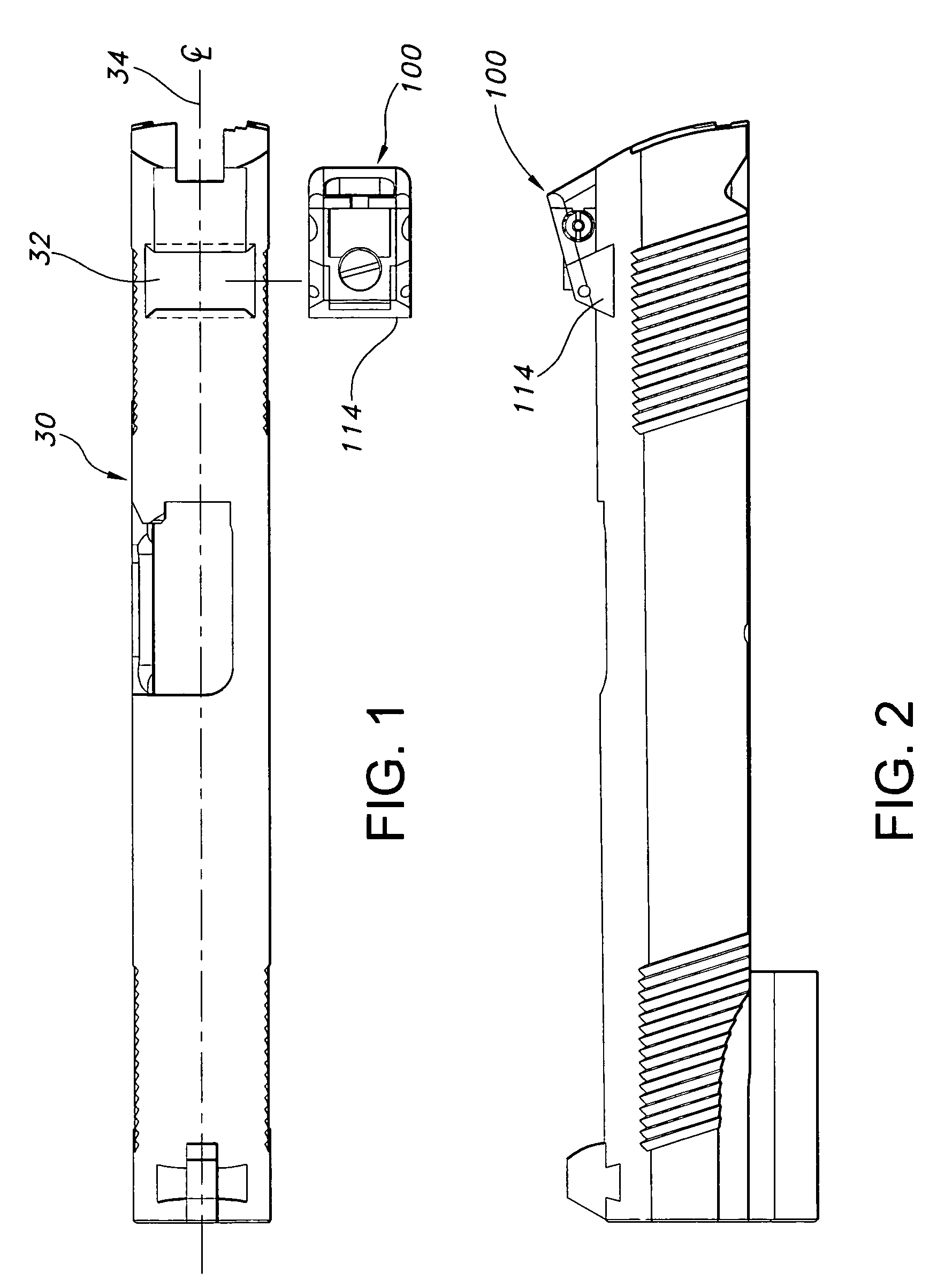
[0047]As best seen in FIGS. 1 and 2, adjustable sight assembly 100 is aligned with Novak-style dovetail notch 32 to permit mounting sight assembly 100 on pistol slide 30. FIG. 2 illustrates a side view of adjustable sight assembly 100 in dovetail notch 32 on pistol slide 30 and shows the orientation of sight base 114 when received within notch 32.

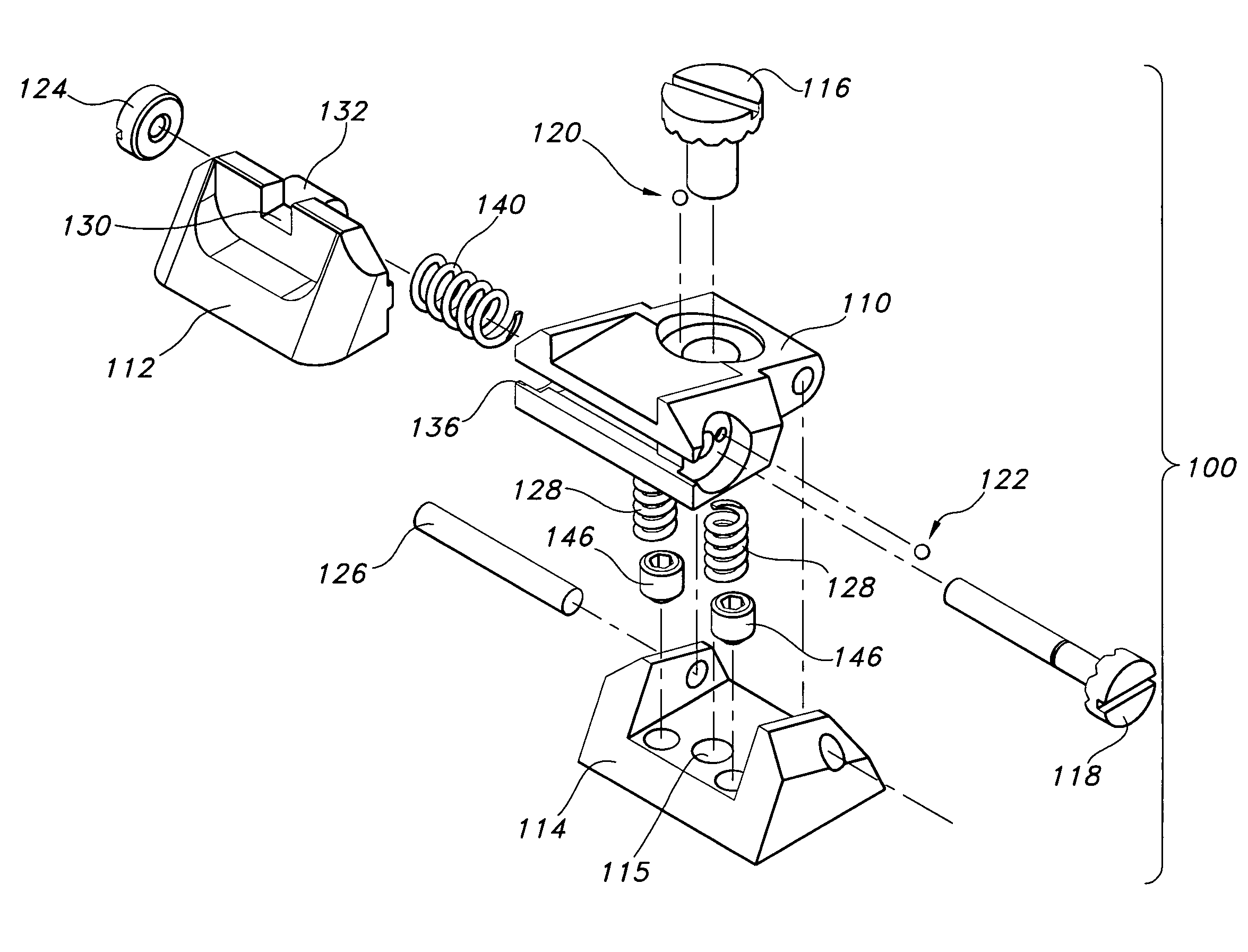
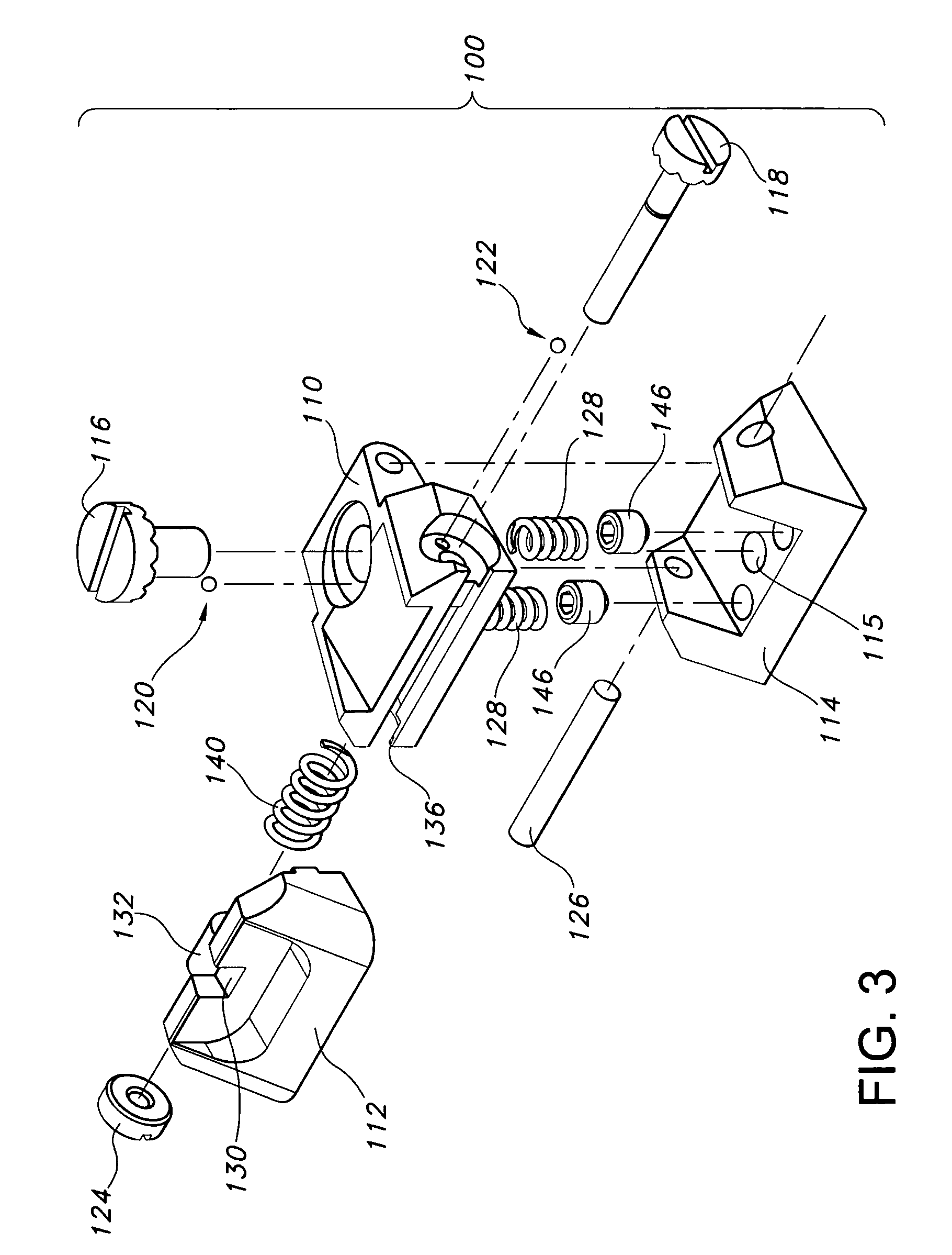
[0048]Referring now to FIGS. 3-11b, in the first embodiment of the adjustable rear pistol sight of the present invention, adjustable sight assembly 100 preferably includes a base 114 with a downwardly-projecting dovetail-shaped member adapted to fit in the pistol's transverse dovetail slot, and base 114 carries a vertical tilt member 110 hinged to rotate about an axis defined by an elevation-tilt hinge pin 126 carried by laterally spaced vertically projecting side walls or bosses on base 114. The vertical translation of the sighting notch 130 (or any other optical alignment structure) is accomplished by adjusting an elevation adjustment scr...

second embodiment

[0057]Referring now to FIGS. 12-23f, in the adjustable rear pistol sight of the present invention, adjustable sight assembly 200 preferably includes a base 214 with a downwardly-projecting dovetail-shaped member adapted to fit in the pistol's transverse dovetail slot, and base 214 carries a vertical tilt member 210 hinged to rotate about an axis defined by an elevation-tilt hinge pin 226 carried by laterally spaced bosses base 214. The vertical translation of the sighting notch 230 (or other optical alignment structure) is accomplished by adjusting an elevation adjustment screw removably received in a threaded bore defined in vertical tilt member 210 and threadably received the base 214. Here again, the elevation adjustment screw 216 has a scalloped head adapted to receive a spring-biased detent pin or rod 220 to provide positive click adjustment to give the user feedback, and to maintain the zero setting during rugged use of the firearm. Vertical tilt member 210 is biased upwardly,...


PUM


Abstract

A rugged, adjustable optical alignment device well suited for use as a pistol rear sight is adapted for use in a dovetail, as is customarily seen on the slide of an automatic pistol. The sight assembly includes a rear notch, but could just as easily include a peep aperture or other optical alignment structure. The rear sight provides an easy click-detent adjusting mechanism for horizontal translation of the notch, as well as a second click-detent mechanism for vertical translation of the structure defining the notch, thereby providing adjustments for windage and elevation. A base hingedly supports a vertical tilt member. A horizontal slide member mounted on the rear of the vertrical tilt member is horizontally translatable by adjustment of a windage adjustment screw.

Description

CROSS-REFERENCE TO RELATED APPLICATIONS AND CLAIM TO PRIORITY[0001]This application claims the benefit (under 35 U.S.C. §§ 119(e) and 120) of U.S. provisional patent application No. 60 / 496,990, filed Aug. 22, 2003, the entire disclosure of which is incorporated herein by reference.BACKGROUND OF THE INVENTION[0002]1. Field of the Invention[0003]The present invention relates to an adjustable optical device such as a pistol sight and a method for mounting and adjusting optical alignment devices such as gun sights on pistols or other firearms.[0004]2. Discussion of the Prior Art[0005]At present, a wide variety of optical sights are available for use on firearms such as pistols.[0006]A typical handgun or pistol has optical alignment fixtures or sights including a front sight and a rear sight which are aligned with one another to form a sight picture for aligning the pistol's point of aim on a target. Prior art pistol sights are usually mounted along the top edge of the pistol. Traditiona...

Claims


Application Information

Patent Timeline
IPC IPC(8): F41G1/00
CPCF41G1/18F41G1/26
Inventor KENG, DAMATUSZCZAK, MACIEJ W.
Owner KENG
Why Eureka
Try Eureka