Motorcycle air intake component cooling system

a cooling system and air intake technology, applied in the field of intake systems, can solve the problems of thermal damage to vehicle parts, ineffective cooling of vehicle parts, and easy rise in temperature inside the cowling, and achieve the effect of effective cooling of vehicle parts

Active Publication Date: 2009-05-05
YAMAHA MOTOR CO LTD
View PDF12 Cites 19 Cited by
  • Summary
  • Abstract
  • Description
  • Claims
  • Application Information

AI Technical Summary

Benefits of technology

[0009]The present invention addresses these issues and provides a motorcycle that effectively cools vehicle parts without a special added cooling duct.
[0011]According to the motorcycle of the present invention, air diverging from the intake system is supplied to the vehicle parts in the vicinity of the engine. Thus, the vehicle parts are cooled down efficiently by the diverging air flow. More specifically, the inside of the intake air passage is kept under relatively high positive pressure because of the dynamical pressure exerted by the running wind, and the temperature is low. Therefore, adequate air flow is obtained without any special cooling duct by branching out the parts cooling system from the engine intake system. As a result, cooling of the vehicle parts is improved without layout space problems, increased numbers of parts, or a more complicated structure.

Problems solved by technology

When a cowling enclosing the front part and left and right sides of the engine is employed, the temperature inside the cowling can rise easily due to heat from the engine, possibly causing thermal damage to vehicle parts.
A structure simply introducing running wind from the introduction port on the cowling may not attain adequate air flow within the cowling, and may not effectively cool down the vehicle parts.
On the other hand, connecting a special cooling duct to the air introduction port on the cowling to supply cooling air to the vehicle parts leads to concerns about additional layout space for the cooling duct, an increase in the number of parts and a more complicated structure as the special cooling duct is disposed.

Method used


Image

  • Motorcycle air intake component cooling system
  • Motorcycle air intake component cooling system
  • Motorcycle air intake component cooling system

Examples


Embodiment Construction

[0018]An embodiment of the present invention is described with reference to the attached drawings.

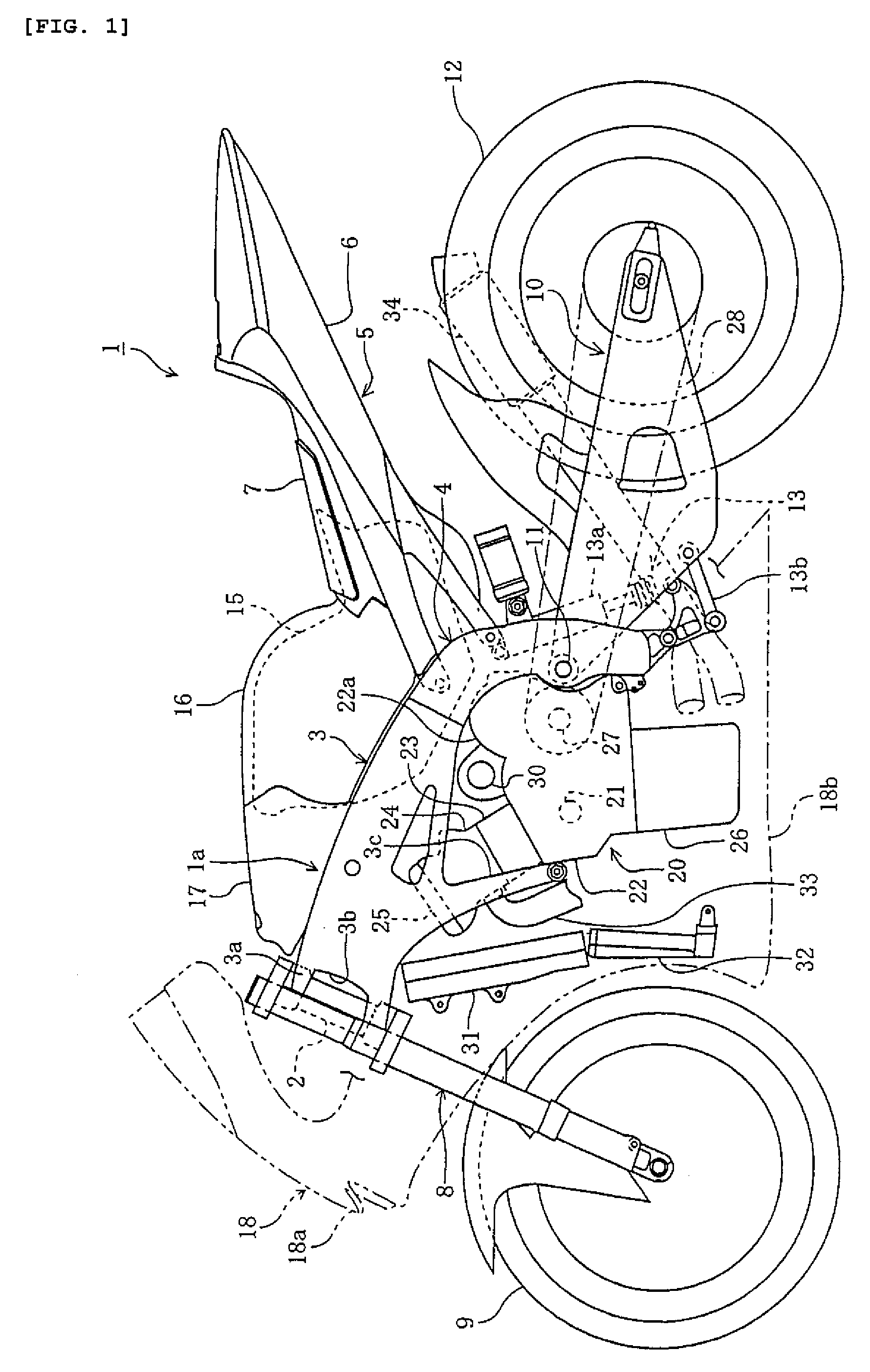
[0019]FIGS. 1-4 illustrate a motorcycle according to an embodiment of the present invention. In the following description, the terms “right,”“left,”“front” and “rear” refer to the right, left, front and rear sides from the perspective of a rider seated on the seat.

[0020]In the drawings, reference numeral 1 denotes a motorcycle having a front wheel 9 and a rear wheel 12 disposed in front of and in the rear of a body frame 1a, respectively, with an engine 20 suspended and supported beneath the body frame 1a. The body frame 1a is covered with a cowling 18 in the areas forward, on the left side, and on the right side of the engine 20.

[0021]The body frame 1a has a head pipe 2, left and right tank rails 3, 3, slanting downward from the head pipe 2 to the rear of the vehicle, and rear arm brackets 4, 4, extending downward from the rear ends of the tank rails 3, 3. A seat 5 is mounted on the re...


PUM


Abstract

A motorcycle that effectively cools vehicle parts without a special cooling duct has a body frame, an engine and an intake system that supplies air to the engine. A parts cooling system makes air diverge from the intake system, and introduces the diverging air to vehicle parts such as electrical parts and an alternator.

Description

RELATED APPLICATIONS[0001]This application claims the benefit of priority under 35 USC 119 of Japanese patent application no. 2005-340814, filed on Nov. 25, 2005, which application is hereby incorporated by reference in its entirety.BACKGROUND OF THE INVENTION[0002]1. Field of the Invention[0003]The present invention relates to an intake system for supplying air to a motorcycle engine.[0004]2. Description of Related Art[0005]In some motorcycles, the front part and left and right sides of an engine are enclosed by a cowling. A duct extending forward is connected to an air cleaner supplying filtered air to the engine, and the duct is connected to an opening formed on the front face of the cowling to introduce running wind into the air cleaner (see JP-A-2000-85664, for example).[0006]When a cowling enclosing the front part and left and right sides of the engine is employed, the temperature inside the cowling can rise easily due to heat from the engine, possibly causing thermal damage t...

Claims


Application Information

Patent Timeline
Patent Type & Authority Patents(United States)
IPC IPC(8): F02P1/02B62J99/00B62K11/04B62M7/02
CPCB62K11/04F02M35/10013F02M35/10268F02M35/162B62J40/10
Inventor TSUYA, KOJI
Owner YAMAHA MOTOR CO LTD
Why Eureka
Try Eureka