Hydrodynamic retarder control apparatus

a technology of hydrodynamic retarder and control apparatus, which is applied in the direction of braking system, braking components, transportation and packaging, etc., can solve the problems of higher oil temperature and energy absorption that is higher than normal

Active Publication Date: 2009-05-05
ALLISON TRANSMISSION INC
View PDF10 Cites 11 Cited by
  • Summary
  • Abstract
  • Description
  • Claims
  • Application Information

AI Technical Summary

Benefits of technology

[0006]It is an object of this invention to provide an improved hydrodynamic retarder control system wherein the regulator valve is assisted by a multi-function valve to prevent excess pressures within the retarder cavity.
[0010]In still another aspect of the present invention, the retarder multi-function valve serves to both energize the retarder system by controlling the retarder flow valve and also by regulating the retarder output pressure in the event of a malfunction in the retarder regulator valve.

Problems solved by technology

These systems work very well under normal operating conditions; however, it is possible for the regulator valve to remain in the open or regulating position due to contamination or other elements that might be found in the fluid.
With this occurring, the retarder cavity can be subjected to higher than needed pressures, which results in higher than normal absorption of energy and higher oil temperatures.

Method used


Image

  • Hydrodynamic retarder control apparatus
  • Hydrodynamic retarder control apparatus
  • Hydrodynamic retarder control apparatus

Examples


Embodiment Construction

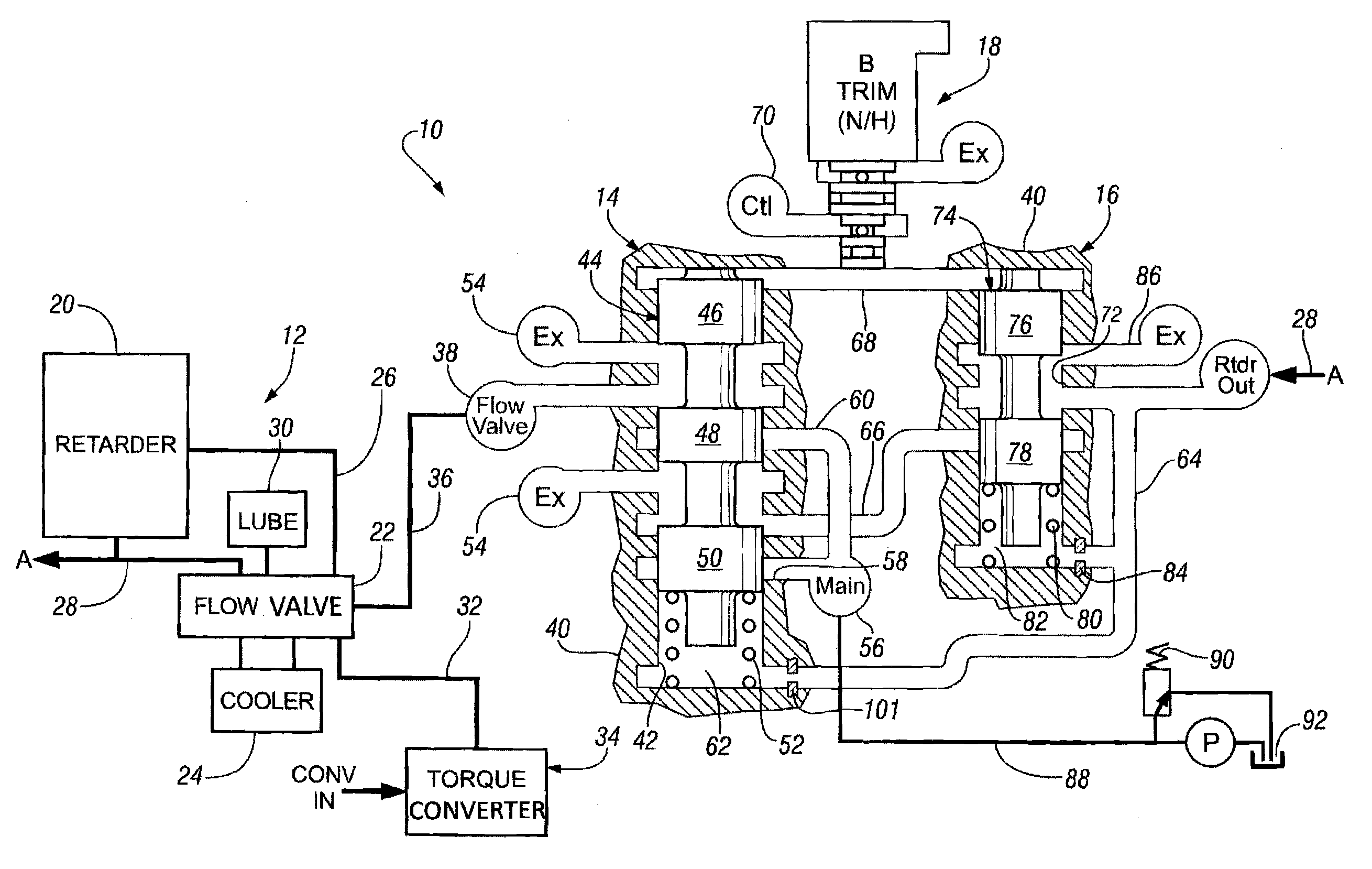
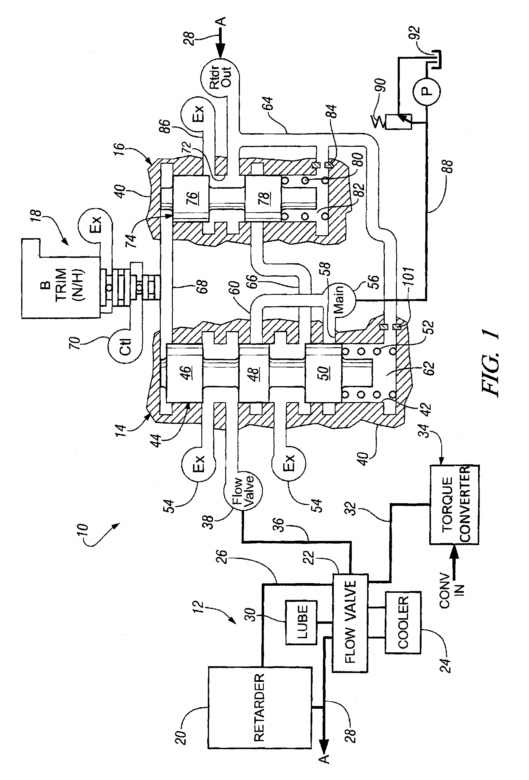
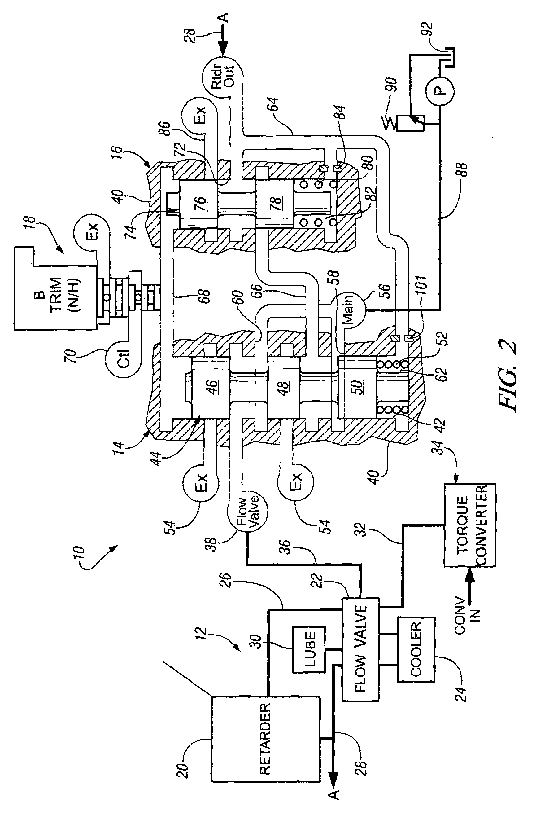
[0014]Referring to the drawings, wherein like characters represent the same or corresponding parts throughout the several views, there is seen in FIG. 1 a hydrodynamic retarder control apparatus 10 having a hydraulic retarder system 12, a retarder multi-function valve 14, a retarder regulator valve 16, and a trim control valve or solenoid 18.

[0015]The hydrodynamic retarder system 12 includes a conventional hydrodynamic retarder 20, a flow valve 22, and a cooler 24. The flow valve 22 is a conventional on / off valve, which controls distribution of fluid from an accumulator, not shown, to a retarder inlet passage 26. The hydrodynamic retarder 20 also has an outlet passage 28, which distributes fluid through the flow valve 22 to the cooler 24 from which it returns back into the flow valve for distribution to passage 26. The flow valve 22 also distributes a portion of the fluid to a lubrication circuit 30. The flow valve 22 also receives fluid from a passage 32, which communicates with a ...


PUM


Abstract

A hydrodynamic retarder control apparatus includes two valve spools, one, a retarder control valve, functions as a relay valve to control the on / off operation of a hydrodynamic retarder and the other, a regulator valve, functions to control the regulation of pressure at the hydrodynamic retarder. During abnormal periods of operation of the regulator valve, the retarder control valve will also function as a pressure control valve thereby limiting the maximum pressure at the hydrodynamic retarder.

Description

TECHNICAL FIELD[0001]This invention relates to control valve apparatus and, more particularly, to control valve apparatus for hydrodynamic retarders.BACKGROUND OF THE INVENTION[0002]Commercial automatic transmissions generally include a hydraulic retarder or hydrodynamic retarder that is used during vehicle braking. These devices absorb energy during vehicle braking and thereby conserve the service brake of the vehicle particularly in downhill operations. The hydrodynamic retarder converts the energy of the driveline into heat and dissipates it using the transmission oil cooling system.[0003]A typical retarder control system consists of a flow valve to direct oil to and from the retarder and a regulator valve to control the pressure in the retarder cavity. The regulator valve generally controls the discharge oil from the retarder. By controlling the retarder pressure, the energy dissipation is also controlled.[0004]These systems work very well under normal operating conditions; howe...

Claims


Application Information

Patent Timeline
Patent Type & Authority Patents(United States)
IPC IPC(8): B60T13/74
CPCB60T10/02
Inventor LONG, CHARLES F.RADER, MARK A.MCCAFFERTY, BRADLEY L.
Owner ALLISON TRANSMISSION INC
Why Eureka
Try Eureka