Connecting profiled element for connecting sheet piles to carrier elements

a profiled element and carrier element technology, applied in the direction of manufacturing tools, mechanical equipment, building scaffolds, etc., can solve the problems of compromising the stability of the combination sheet pile wall or its leakage tightness in these locations, and achieve the effect of erection and erection more easily

Active Publication Date: 2009-05-05
SHEET PILE LLC
View PDF13 Cites 34 Cited by
  • Summary
  • Abstract
  • Description
  • Claims
  • Application Information

AI Technical Summary

Benefits of technology

[0005]It is, therefore an object of the invention to provide a connecting profiled element or a combination sheet pile wall, with such a connecting profiled element, respectively, that when used a combination sheet pile wall can be erected more easily, or that can be erected more easily compared to known combination sheet pile walls.
[0007]The design of the receiving profiled element for the interlock of a sheet pile to be connected according to the invention, in particular a sheet pile to be connected using LARSSEN interlocks, has the effect that the interlock can be pivoted in a wide range in the receiving profiled element. The potential pivoting angle is in a range of more than 60°. With such a large pivoting angle, it is possible that when erecting a combination sheet pile wall, the adjacent carrier elements, e.g., I-beams can be twisted at a large angle in relation to each without tension arising in the combination sheet pile wall when ramming the sheet piles into the ground. These potential large pivoting angles between carrier elements and sheet piles allow also to erect a sheet pile wall with a large pivoting angle between adjacent wall sections such that no additional connecting elements are required in such a sheet pile wall.
[0008]The large potential pivoting angles between connecting profiled elements, carrier elements and sheet piles also avoids the high tensions resulting from ramming the individual elements into the ground that could otherwise lead to the disengaging of the engaged interlocks of the carrier elements, the sheet piles and the connecting profiled elements, which could compromise the stability of the combination sheet pile walls or their leak tightness in these locations.
[0010]In addition, the connecting profiled element subject to the invention allows for large pivoting angles in the combination sheet pile wall between adjacent carrier elements, in particular I-beams, for the sheet piles used. Pivoting can occur between adjacent carrier elements or between the sheet piles and the carrier elements hooked into them, for example when the carrier elements are rammed into the ground if the ground has irregular soil conditions due to rock formations, erratics or the like. Because of this, the carrier elements and sheet piles may be twisted at their longitudinal axis when rammed into the ground. Such twisting or torsion is compensated for by the design of the connecting profiled elements subject to the invention. By contrast, conventional connecting profiled elements often allow only a very limited pivoting angle such that the sheet piles disengage from the connecting profiled elements when rammed into the ground and the sheet pile wall is left untight in particular to liquids at these locations. Furthermore, the stability of the sheet pile wall is no longer given to the calculated extent if the interlocks of the sheet piles disengage from the connecting profiled elements during the ramming process.
[0013]For attaching sheet piles, in particular sheet piles with LARSSEN interlocks, a sufficiently large jaw must be provided at the connecting profiled element such that on the one hand the sheet pile can easily be inserted into the attachment profiled element, and on the other hand, the interlock does not disengage from the attachment profiled element during the ramming process. Essentially, this is achieved in that the connecting profiled element surrounds the interlock of the sheet pile to be attached in a generous and wide manner and whereby it is ensured that for the extreme pivoting angles between the connecting profiled element and the attached sheet pile, a three-point connection is established at all times between said two components. Such a three-point connection prevents the disengaging of the engaging interlocks during the ramming process, such that the stability of the combination sheet pile wall and its leak tightness remain ensured.
[0019]In an additional particularly preferred embodiment of the connecting profiled element according to the invention, the plug-in profiled element and the receiving profiled element are formed at the central strip offset in relation to one another. The effect of this is that the carrier element and the sheet pile can be connected to each other offset to one another in order to achieve an as smooth as possible contour of the combination sheet pile wall along a specified direction.

Problems solved by technology

The large potential pivoting angles between connecting profiled elements, carrier elements and sheet piles also avoids the high tensions resulting from ramming the individual elements into the ground that could otherwise lead to the disengaging of the engaged interlocks of the carrier elements, the sheet piles and the connecting profiled elements, which could compromise the stability of the combination sheet pile walls or their leak tightness in these locations.

Method used


Image

  • Connecting profiled element for connecting sheet piles to carrier elements
  • Connecting profiled element for connecting sheet piles to carrier elements
  • Connecting profiled element for connecting sheet piles to carrier elements

Examples


Embodiment Construction

[0029]The preferred embodiments of the present invention will now be described with reference to FIGS. 1-7 of the drawings. Identical elements in the figures are designated with the same reference numerals.

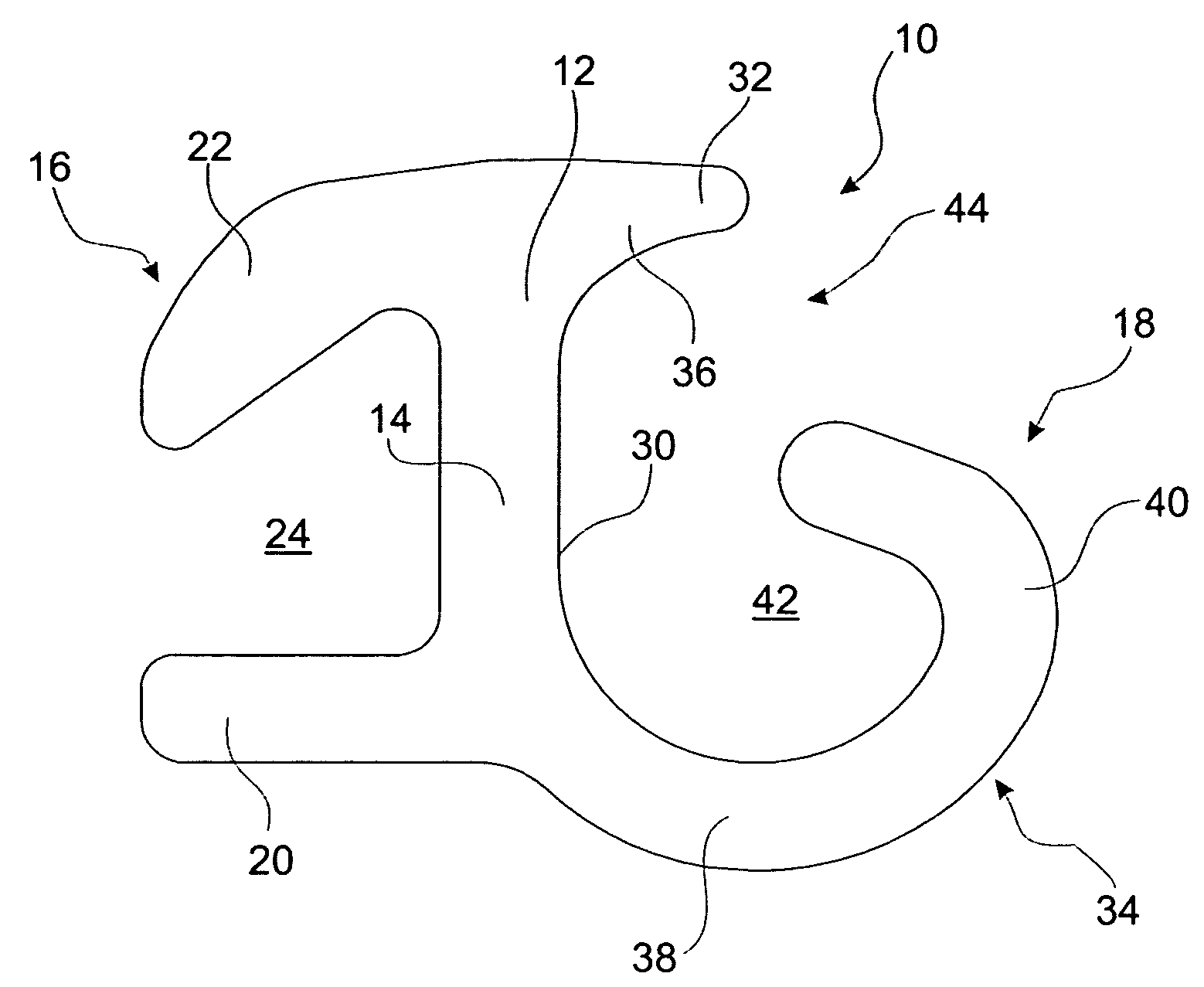
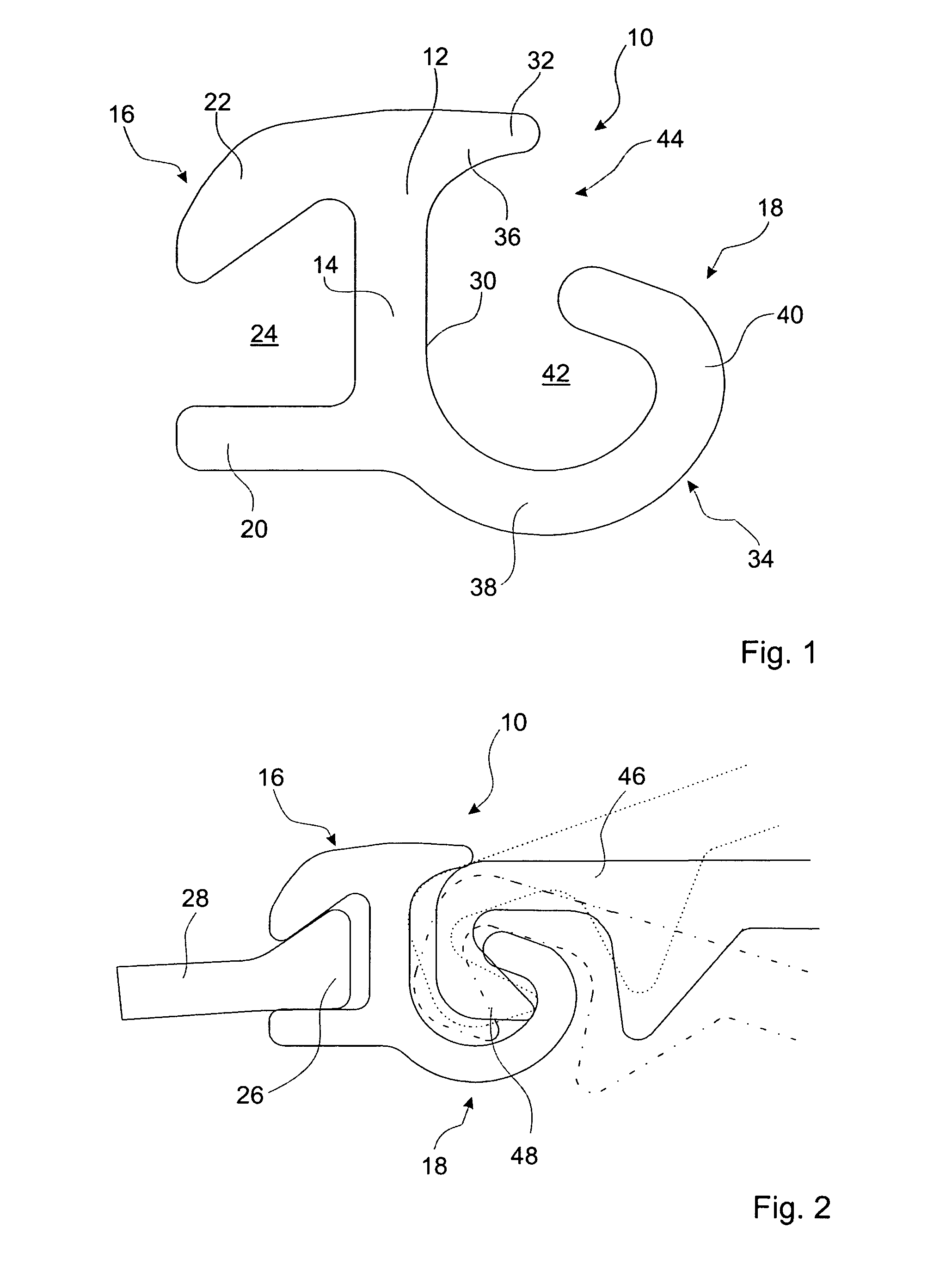
[0030]FIGS. 1 and 2 show an exemplary embodiment of a connecting profiled element 10 subject to the invention. The connecting profiled element 10 exhibits a central strip 12 with a straight, flat central section 14 that separates two attachment profiled elements, a plug-in profiled element 16 and a receiving profiled element 18 from each other.

[0031]The plug-in profiled element 16 is defined by the central strip 12, a first straight jaw strip 20, which issues from the lower edge shown in FIG. 1 at an angle of 90° and a second bent jaw strip 22, which issues from the other side of the central strip 12 in the direction of the first straight jaw strip 20. The two jaw strips 20 and 22 end in a plane that runs somewhat parallel to the central strip 12 and form together with said centra...


PUM


Abstract

A rod-type connecting profiled element (10) for connecting sheet piles to carrier elements comprises a central strip (12) that separates two opposing connecting profiled elements (16, 18), each of which respectively forms a saw (24, 42). One connecting profiled element is embodied as a plug-in profiled element (16) for the carrier element and the other connecting profiled element is embodied as a receiving profiled element (18) for connecting a sheet pile. The central strip (12) comprises, on the side of the receiving profiled element (18), a central section (14) having a straight plane inner wall (30) to which a first short end section (32) is connected on one side, said short end section protruding past the central section (14) at an angle of approximately 90°, and being connected thereto by means of a transition section (36) having an inner wall with a cross-section that follows a quadrant. A hook strip (34) is arranged on the other side of the plane central section (14) as a second end section oriented in the same direction as the first end section (32).

Description

BACKGROUND OF THE INVENTION[0001]The invention concerns a connecting profiled element according for attaching sheet piles to carrier elements, in particular to an I-beam. In addition, the invention according to the main subject of claim 13 also concerns a combination sheet pile wall with such a connecting profiled element.[0002]So-called “combination sheet pile walls” can be built with carrier elements, sheet piles and the connecting profiled elements described above, whereby one or more sheet piles are used between two adjacent carrier elements. To connect the carrier elements to the sheet piles, a connecting profiled element is used with a central strip that separates two attachment profiled elements, which are designed in an opposite manner, using a jaw, and that is a part of both attachment profiled elements. The one profiled element is typically designed as a plug-in profiled element for the carrier element, and the other attachment profiled element as a receiving profiled elem...

Claims


Application Information

Patent Timeline
Patent Type & Authority Patents(United States)
IPC IPC(8): E02D5/02E02D17/00E02D5/06
CPCE02D5/06Y10T403/73F16B2200/67
Inventor HEINDL, RICHARDWENDT, ROB R.WALL, GEORG
Owner SHEET PILE LLC
Why Eureka
Try Eureka