Wind turbine with current conducting means, which are pre-assembled in the tower

a technology of current conducting means and wind turbines, which is applied in the direction of wind energy generation, motors, electrical equipment, etc., can solve the problems of costly process, and achieve the effect of reducing process costs, facilitating installation and reducing labor intensity

Inactive Publication Date: 2007-04-03
WOBBEN ALOYS
View PDF25 Cites 17 Cited by
  • Summary
  • Abstract
  • Description
  • Claims
  • Application Information

AI Technical Summary

Benefits of technology

[0003]This invention is based on providing a wind energy plant that can be erected more easily and thus also cheaper and faster.

Problems solved by technology

This is a costly process, since the cable has to be installed over the entire height of the tower in a separate work cycle.

Method used


Image

  • Wind turbine with current conducting means, which are pre-assembled in the tower
  • Wind turbine with current conducting means, which are pre-assembled in the tower
  • Wind turbine with current conducting means, which are pre-assembled in the tower

Examples


Embodiment Construction

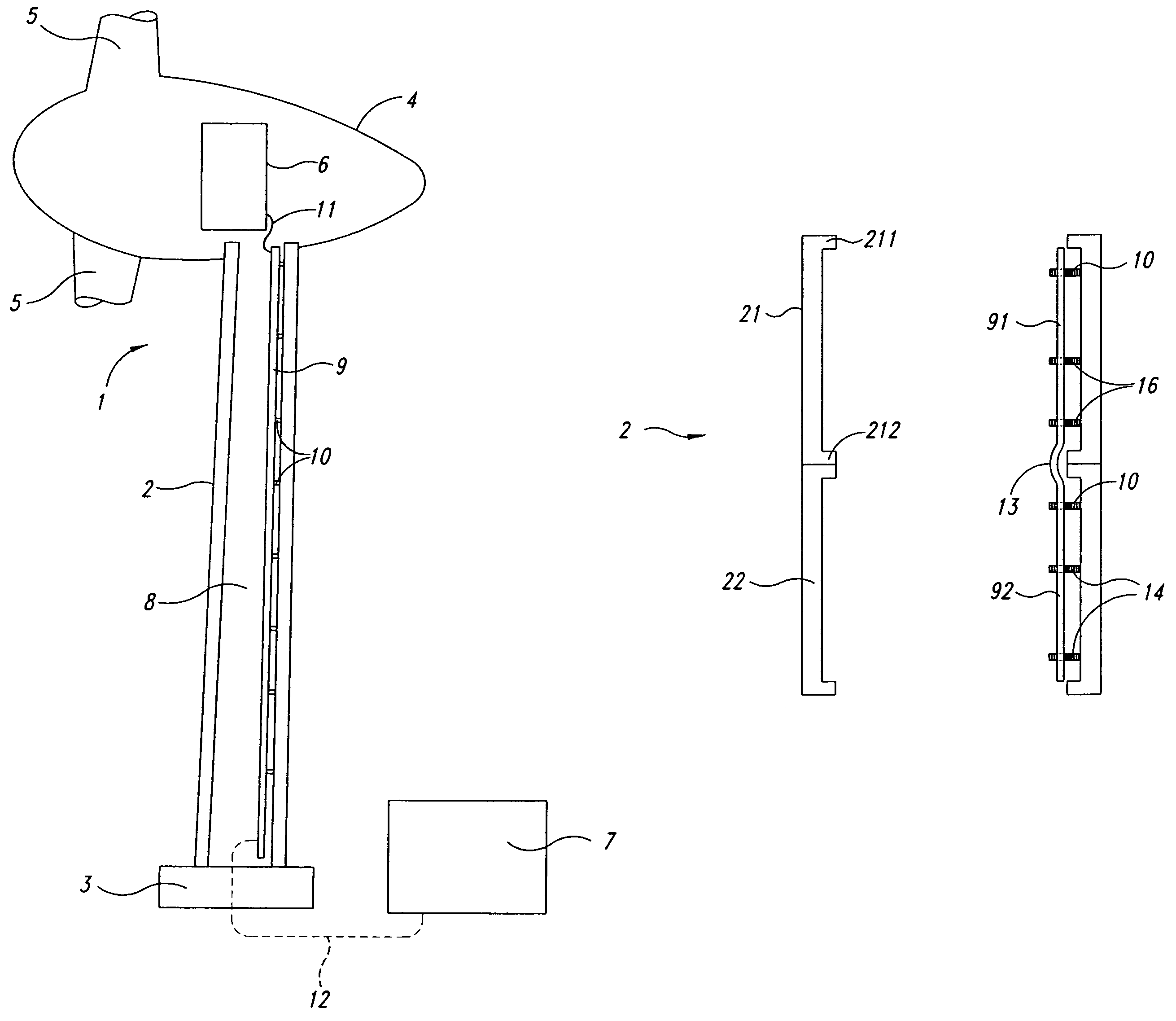
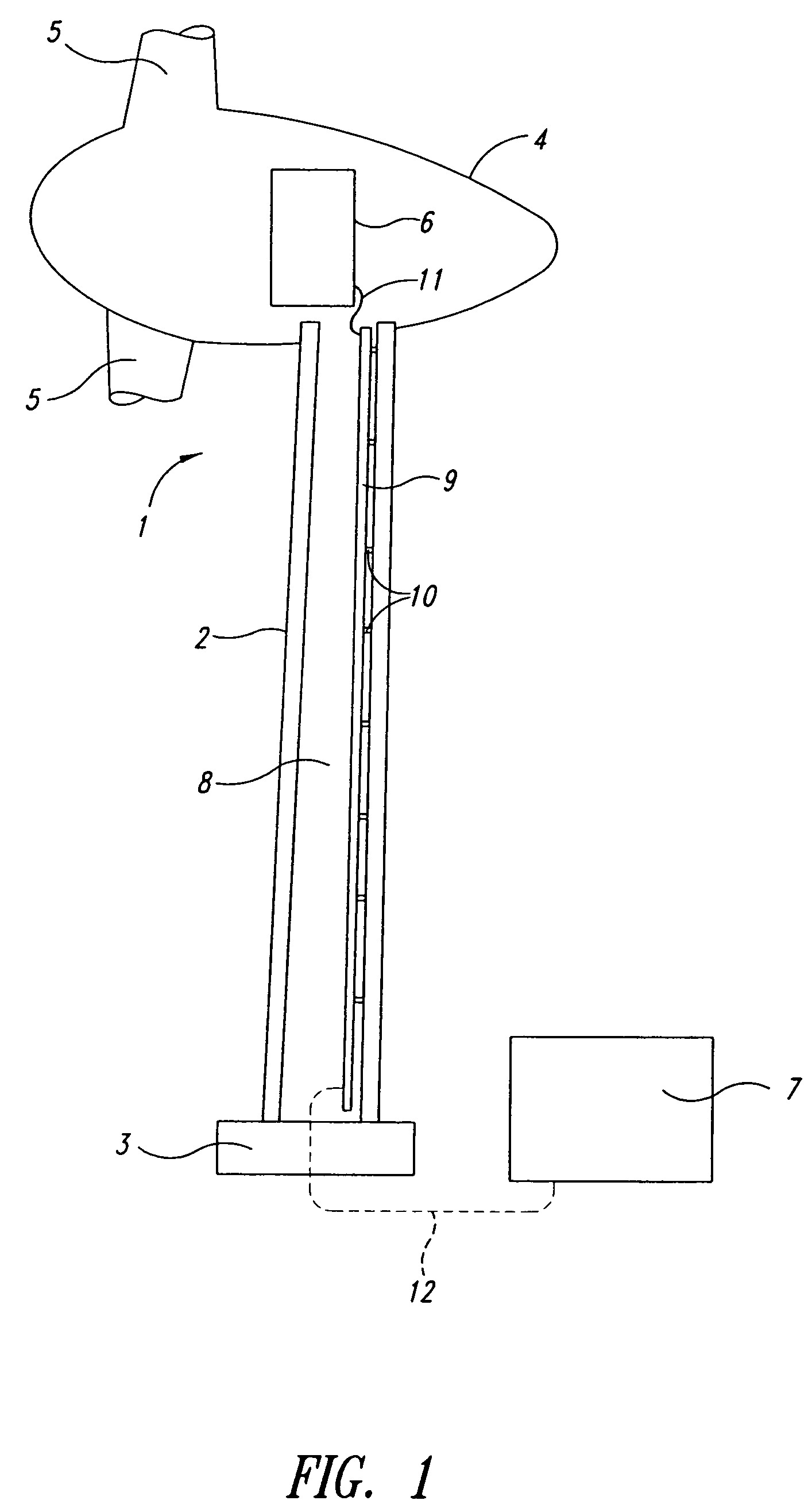
[0015]The wind energy plant 1 in accordance with the present invention that is shown schematically in FIG. 1 has a tower 2 with foundation 3, a gondola 4 that is positioned with the possibility of rotation in the region of the top of the tower and a power module 7 arranged in the region of the base of the tower, for example in a separate housing. A rotor with several rotor blades 5, which can rotate about a horizontal axis, and an electrical generator 6 are arranged within the gondola 4. Wind forces acting on the rotor blades 5 set the rotor in motion and drive generator 6 to produce electrical energy.

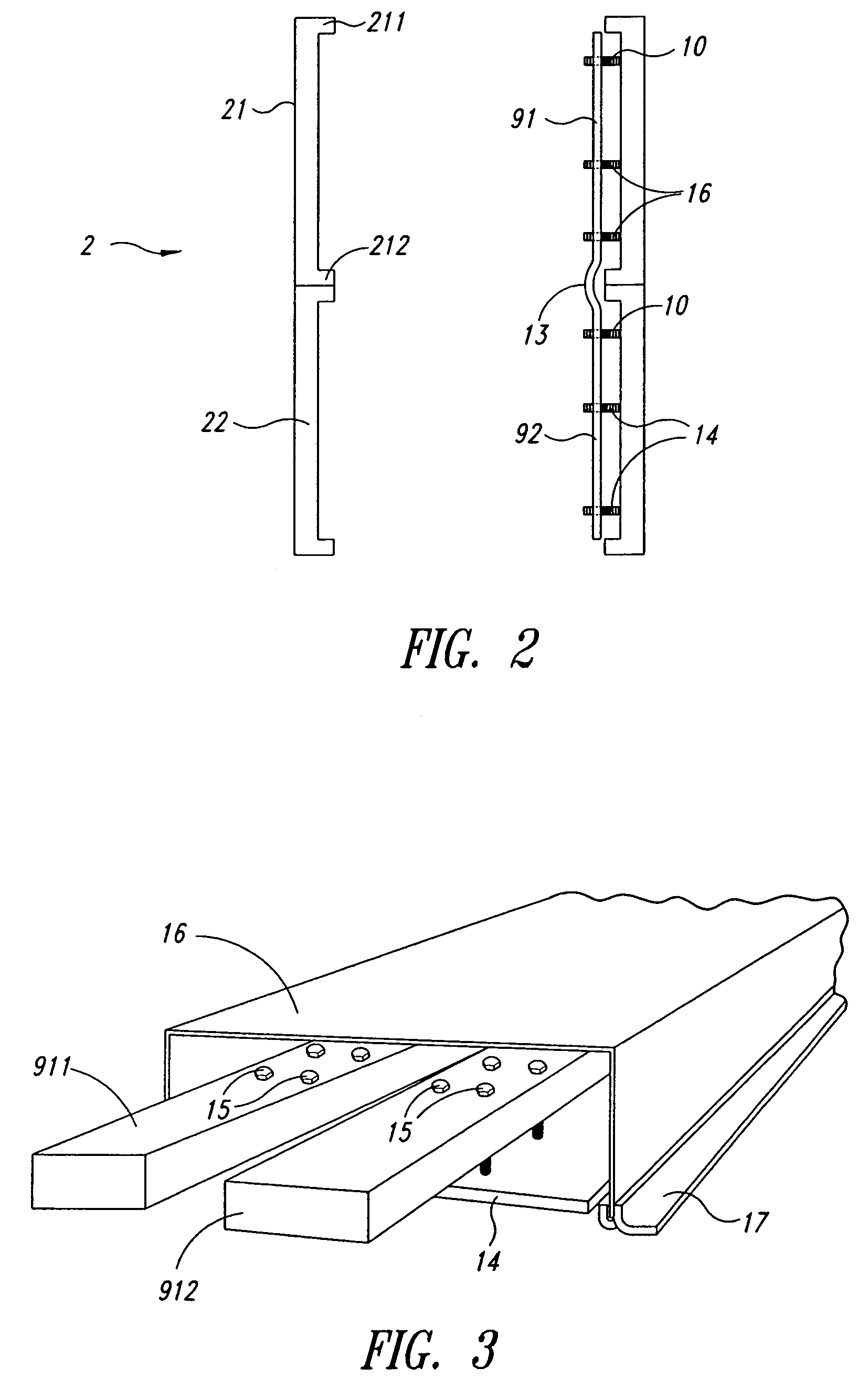
[0016]To transfer the energy produced by generator 6 to the power module 7, which has numerous electrical units, such as a transformer or optionally a rectifier for processing the electrical current, before it is sent to the power network or to a user, there are provided current buses, preferably two current buses, in the inside space 8 of tower 2 at the wall by means of fastening elem...


PUM


Abstract

The present invention concerns a wind energy plant for generation of alternating current with a tower constructed of several tower segments, a generator arranged in the region of the top of the tower, a power module arranged in the region of the base of the tower, and current carrying means for transferred current from the generator to the power module. In order to enable faster, easier and thereby cheaper erection of the wind energy plant, it is provided in accordance with the present invention that the current carrying means be premounted in the tower segments in segmented form.

Description

FIELD OF THE INVENTION[0001]The present invention concerns a wind energy plant with a tower formed of a number of tower segments, with a generator arranged in the region of the tower head, with a power module arranged in the region of the tower base and with current carrying means to transfer the current from the generator to the power module.BACKGROUND OF THE INVENTION[0002]The electrical power module of a wind energy plant, which includes electrical units such as transformers, control boxes, optionally rectifiers, medium voltage plants, low voltage distributors, etc., is arranged underneath the level of the generator as in the case of the known wind energy plants and commonly is in the region of the base of the tower of the wind energy plant. Most often a separate small building outside the wind energy plant is provided for this module or for some of these components. Current carrying means, which most often run within the tower and are designed as cables, are provided to carry th...

Claims


Application Information

Patent Timeline
Patent Type & Authority Patents(United States)
IPC IPC(8): F03D9/00H02P9/04F03D9/25F03D11/00F03D13/10F03D80/00F03D80/80
CPCF03D11/00F05B2240/912H02G5/002Y02E10/728Y02E10/722F03D9/25F03D9/255F03D13/10F03D80/00F03D80/82F03D80/85F05B2240/14F05B2240/95Y02E10/72Y02E10/727
Inventor WOBBEN, ALOYS
Owner WOBBEN ALOYS
Why Eureka
Try Eureka