Turbine airfoil with mini-serpentine cooling passages

a cooling passage and turbine airfoil technology, which is applied in the field of fluid reaction surfaces, can solve the problems of low convective cooling effectiveness, low convective cooling efficiency, and difficulty in achieving the control of the cooling flow of the airfoil external hot gas temperature and pressure variation, and achieve the effect of increasing the internal convection cooing effectiveness and maximizing the use of cooling air

Inactive Publication Date: 2009-05-05
FLORIDA TURBINE TECH
View PDF7 Cites 81 Cited by
  • Summary
  • Abstract
  • Description
  • Claims
  • Application Information

AI Technical Summary

Benefits of technology

[0010]The present invention is a turbine airfoil having a plurality of small modules each having a mini-serpentine cooling flow passage to provide near wall chordwise cooling of the airfoil wall. The airfoil includes an outer airfoil surface and an inner wall having three radially oriented cooling passages therein. Positioned between the outer airfoil surface and the inner wall surface are the mini-serpentine modules. Each module can be a three pass or five pass serpentine passage with an inlet connected to one of the internal radial cooling passages and an outlet connected to a film cooling holes opening onto the outer airfoil surface to provide film cooling. The mini-serpentine modules are formed within the outside surface of the inner wall of the airfoil and extend along in the chordwise direction of the airfoil. The individual modules are designed based on the airfoil gas side pressure distribution in both the chordwise and the spanwise directions. In addition, each ind

Problems solved by technology

As a result of this cooling construction approach, spanwise and chordwise cooling flow control due to airfoil external hot gas temperature and pressure variation is difficult to achieve.
In addition, a single radial channel flow is not the best method of utilizing cooling air that results in low convective cooling effectivenes

Method used


Image

  • Turbine airfoil with mini-serpentine cooling passages
  • Turbine airfoil with mini-serpentine cooling passages
  • Turbine airfoil with mini-serpentine cooling passages

Examples


Embodiment Construction

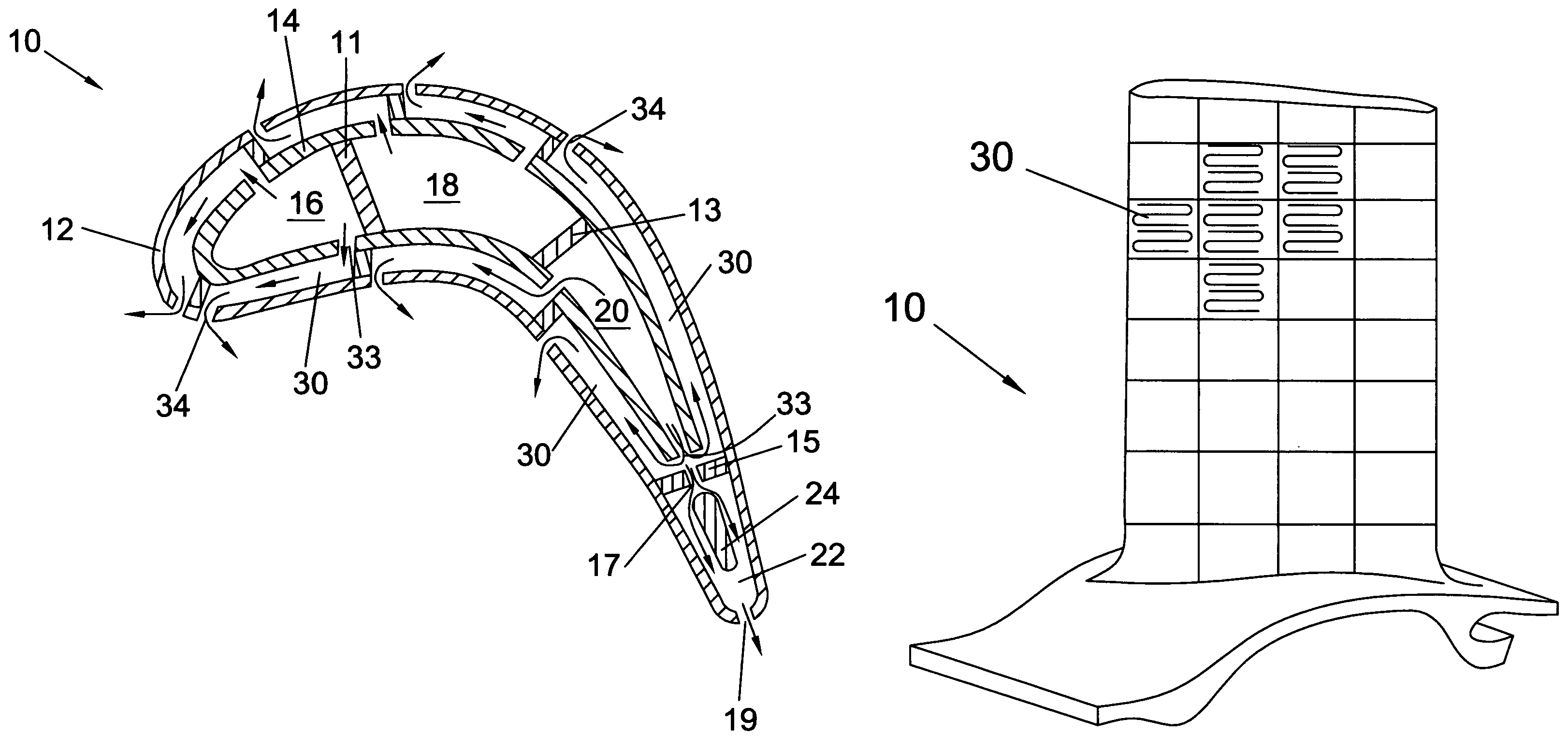
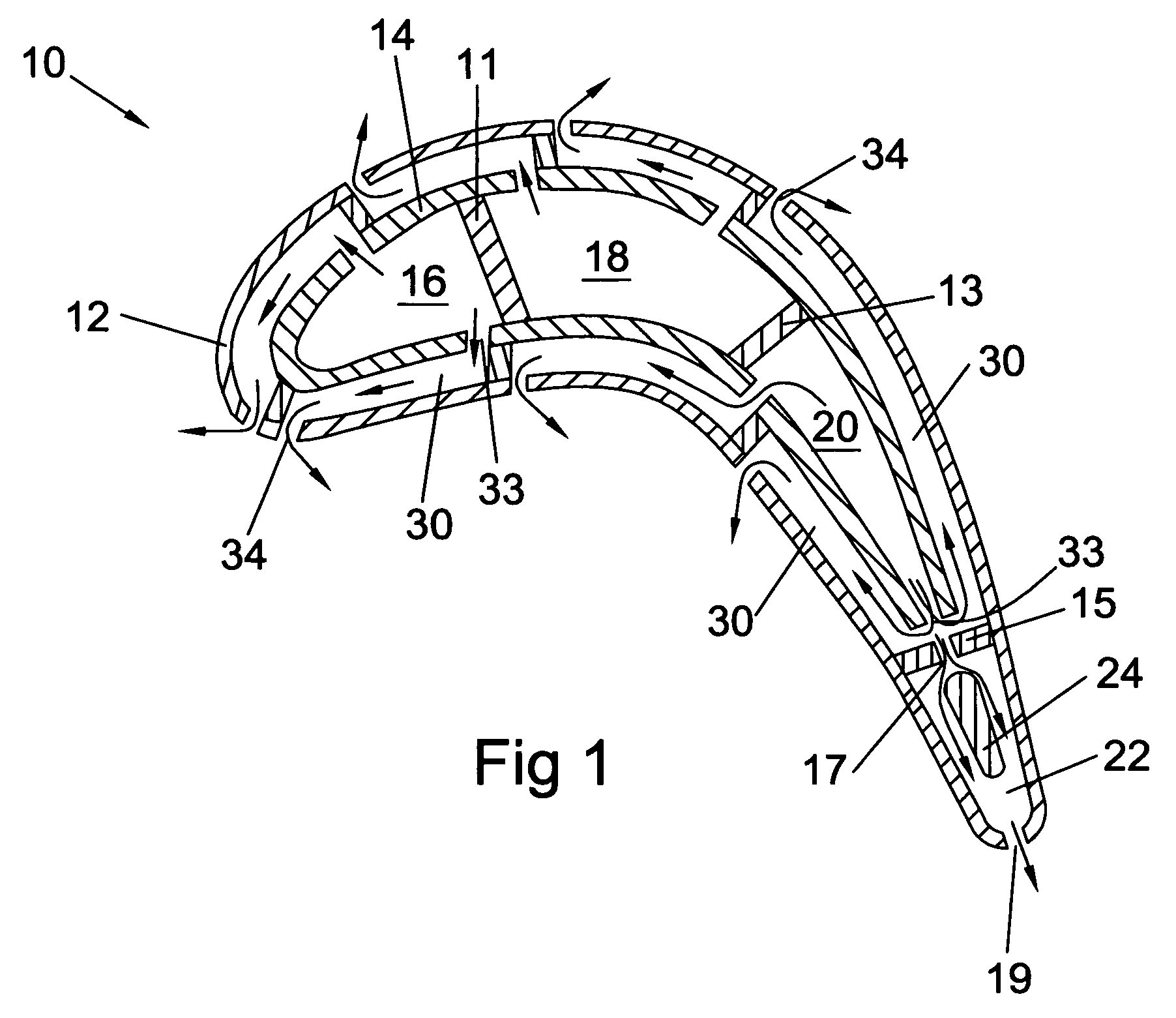
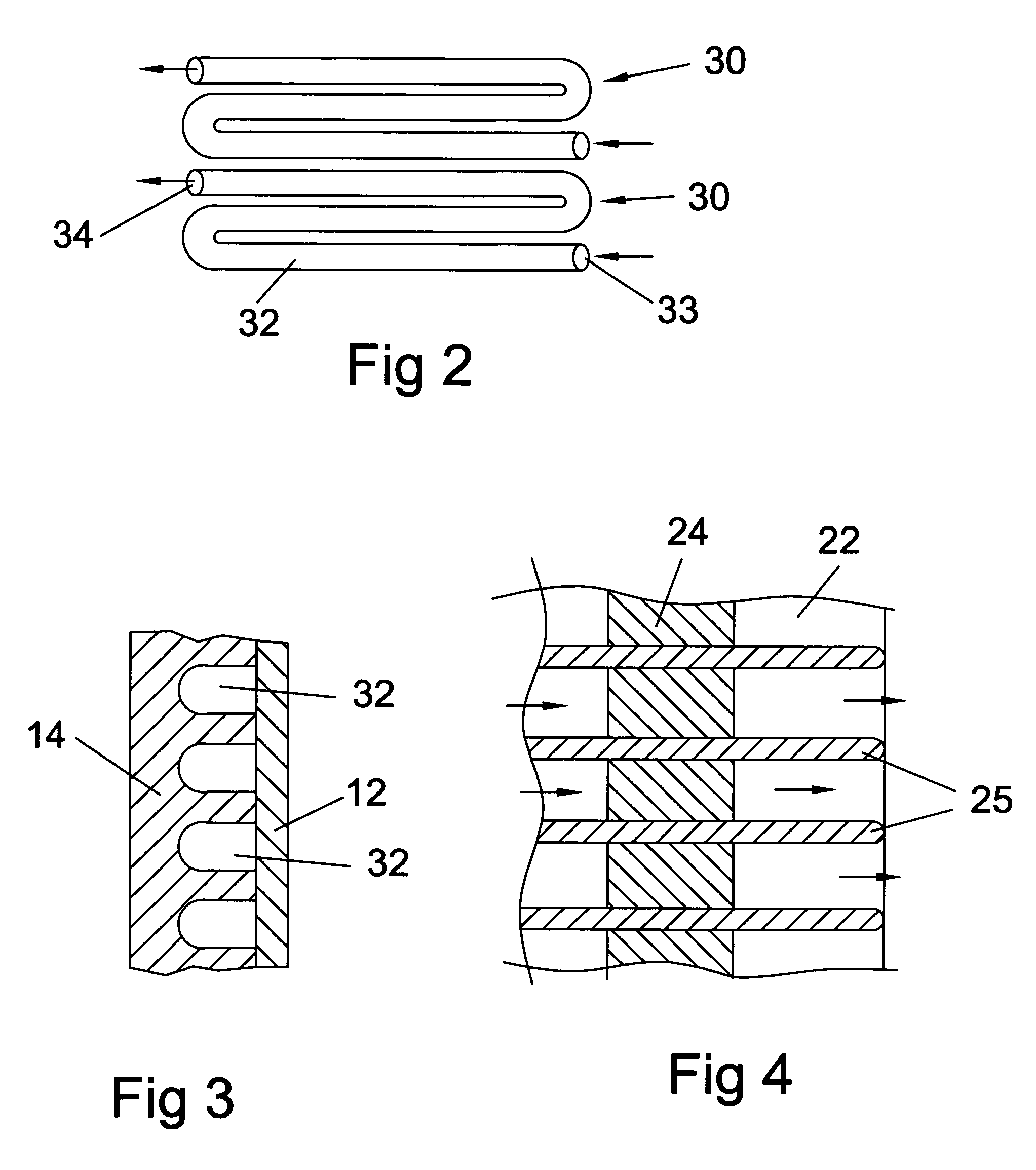
[0016]The present invention is an airfoil used in a gas turbine engine, the airfoil having an internal cooling flow passage to provide cooling to the airfoil that operates under extreme high temperatures that would normally damage the airfoil without the cooling. The airfoil can be a stationary vane or nozzle in the first or second stage, or a first or second stage rotary blade used in the turbine. A cross section of the airfoil 10 is shown in FIG. 1. An outer airfoil surface 12 forms the general airfoil surface on which the hot gas flow acts thereon. An inner wall airfoil surface 14 is positioned within the outer airfoil surface 12 and includes three radial cooling channels. A leading edge radial cavity 16 provides cooling air to the leading edge portion of the airfoil, a middle radial cooling cavity 18 provides cooling air to the middle portion of the airfoil, and a trailing edge or mid-chord radial cooling cavity 20 provides cooling air to the trailing edge portion of the airfoil...


PUM


Abstract

An airfoil used in a gas turbine engine, especially a large rotor blade in an industrial gas turbine engine, the airfoil having at least one cooling air supply cavity formed by an inner wall of the airfoil to supply cooling air to the airfoil, and a plurality of mini-serpentine cooling modules formed between the inner wall and the outer wall surface of the airfoil providing near-wall cooling for the airfoil. The modules includes three-pass or five-pass serpentine cooling channels with an inlet in fluid communication with the cooling air supply cavity and an outlet opening onto the airfoil surface to provide film cooling to the airfoil. The length of a straight section of the passage is about 5 to 10 mm and about 1 mm in diameter. A plurality of supply cavities are formed within the inner wall and separated by ribs. A plurality of mini-serpentine cooling modules is arranged along a chordwise length of the airfoil and each is in fluid communication with the nearest supply cavity.

Description

BACKGROUND OF THE INVENTION[0001]1. Field of the Invention[0002]The present invention relates to fluid reaction surfaces, and more specifically to turbine airfoils with internal cooling passages.[0003]2. Description of the Related Art Including Information Disclosed Under 37 CFR 1.97 and 1.98[0004]A gas turbine engine burns a fuel to produce a hot gas flow which is passed through a turbine to produce mechanical work. A compressor delivers compressed air to a combustor to be mixed with a fuel to burn. The resulting hot gas flow is directed through a multiple stage turbine to convert the hot gas flow into rotation of the turbine to drive the compressor. In an Industrial Gas Turbine (IGT), the turbine shaft is also used to drive a motor such as an electrical generator. In an aero gas turbine engine, the exhaust is used to propel the airplane.[0005]An efficiency of the gas turbine engine can be improved by operating at a higher hot gas flow temperature. However, the highest temperature ...

Claims


Application Information

Patent Timeline
IPC IPC(8): F01D5/18
CPCF01D5/186F01D5/189F05D2250/185Y02T50/676Y02T50/60
Inventor LIANG, GEORGE
Owner FLORIDA TURBINE TECH
Why Eureka
Try Eureka