External fixation element

a technology of external fixation elements and fixing elements, applied in the direction of magnetic variable regulation, prosthesis, invalid friendly devices, etc., can solve problems such as vibration or movement of devices

Active Publication Date: 2009-05-05
STRYKER EURO OPERATIONS HLDG LLC
View PDF16 Cites 93 Cited by
  • Summary
  • Abstract
  • Description
  • Claims
  • Application Information

AI Technical Summary

Benefits of technology

[0007]In view of this prior art, one aspect of the invention is to provide external fixation elements, wherein a patient carrying such a structure can safely be examined within a MRI device.

Problems solved by technology

Furthermore, a torque may be generated resulting in a vibration or movement of the device.

Method used


Image

  • External fixation element
  • External fixation element
  • External fixation element

Examples


Embodiment Construction

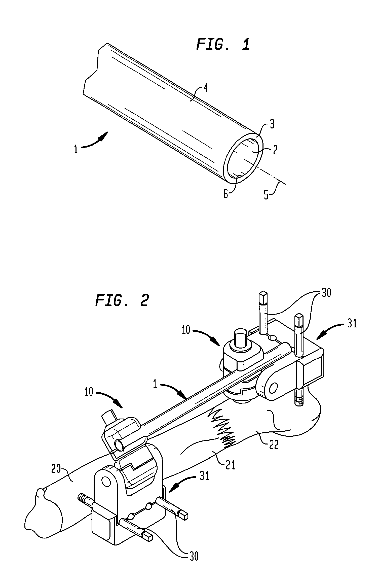
[0018]FIG. 1 shows a schematic view of rod 1 for use in an external fixation device. The core has received the reference numeral 2. A non-conductive sheath 3 encloses the core 2. The cylindrical surface 4 of the sheath may be smooth or comprise a grid of high spots. Preferably rod 1 is available with different diameters depending on its use in an external fixation device, e.g. as thicker rods 1 and thinner pins 30 as shown in FIG. 2.

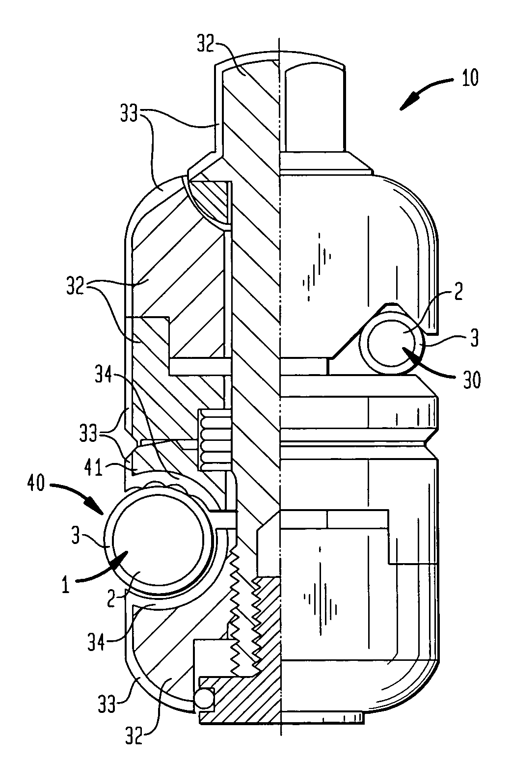
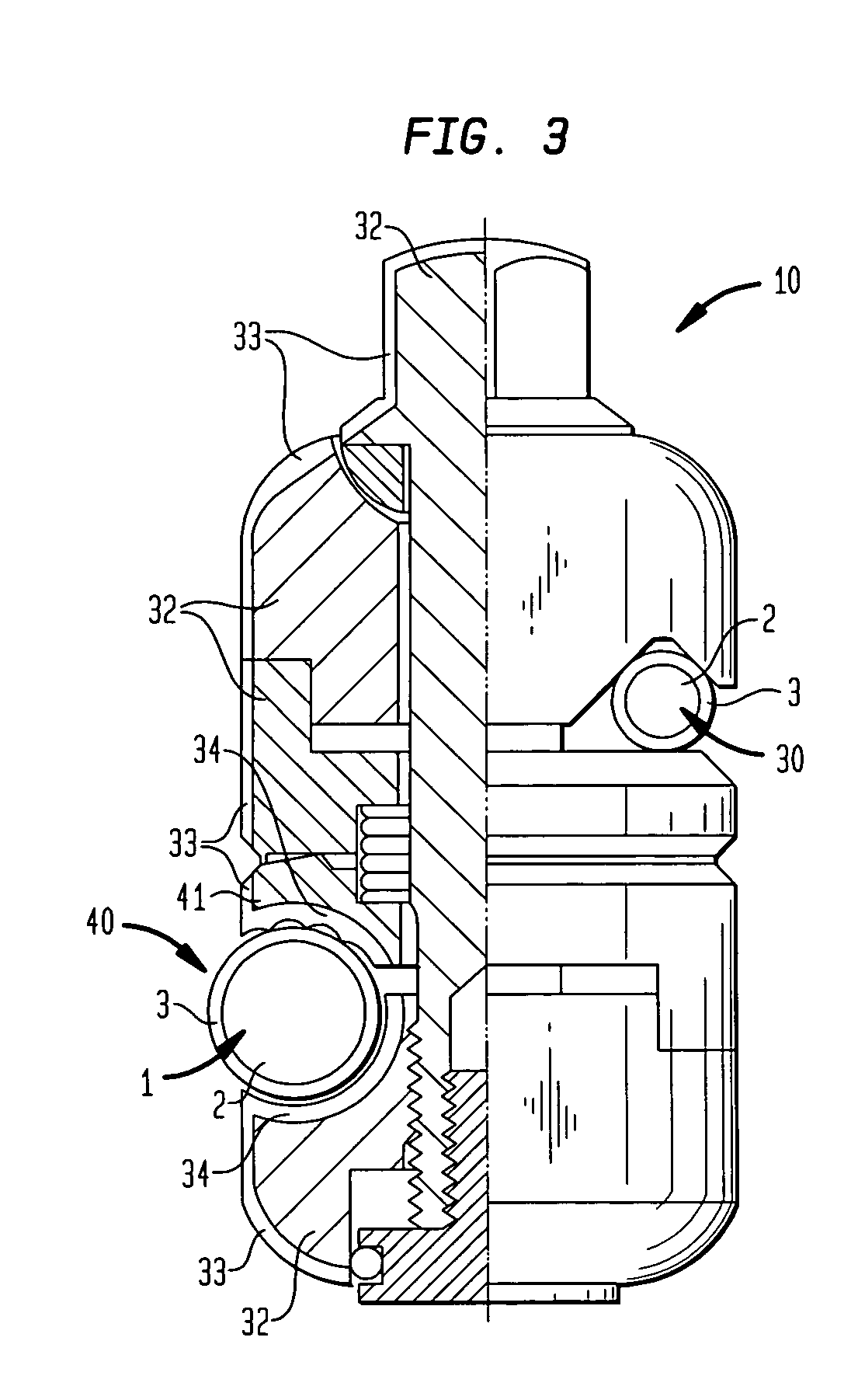
[0019]The rod 1 according to the invention is to be used with further elements of an external fixation system or frame, e.g. clamps 10 and 31 as shown in FIG. 2. FIG. 2 shows a schematic view of the use of an external fixation system with a broken bone 20 using several fixation elements according to the invention. Pins 30 are drilled into the bone parts 21 and 22, respectively and held within clamp parts 31. The clamp parts 31 are mounted together with clamps 10. The two clamps 10 are connected via the rod 1 oriented mainly in parallel to the broken limb...


PUM


Abstract

An external fixation system has clamps, rods and pins having anti-magnetic core parts and a non-conductive sheath part covering essentially the exterior surfaces of the core part. The rods, pins and clamps are especially MRI safe for a patient when used in any frame configuration for fractures of the upper and lower extremities and pelvis wherein the usual MRI field parameters of a static field of 2 Tesla, a time-varying filed of max. 20 Tesla / sec and a specific absorption rate (SAR) of max. 0.4 Watts / kg averaged over the whole body of the patient apply.

Description

BACKGROUND OF THE INVENTION[0001]This invention relates to external fixation elements, especially to external fixation rods. More particularly, it relates to an apparatus and method to make use of such elements safer during MRI procedures.[0002]Magnetic Resonance Imaging (MRI) is a well known diagnostic tool in the field of medicine. It is equally known to surgeons that problems may occur for patients wearing metallic devices inside or outside their body during examination with a MRI device (inside or outside the coil).[0003]It is known in the prior art, e.g. from FR 2 703 580, to use antimagnetic implants, e.g. made in polyethylene, and to use additional radiopaque markers to get an image of the implant. This makes such an implant MRI-safe.[0004]U.S. Publication No. 2002 / 042619 discloses a headframe for use with a stereotactic system. It is mentioned in the last paragraph of the description that the frame body and swivel arms need not to be made from aluminum. Instead, the frame bo...

Claims


Application Information

Patent Timeline
Patent Type & Authority Patents(United States)
IPC IPC(8): A61B17/56A61B5/055A61B17/60G01R33/28A61B17/64A61B17/86
CPCA61B17/60A61B17/6466A61B17/866
Inventor LUTZ, CHRISTIANBURGHERR, VINZENZPALEFROY, OLIVIER
Owner STRYKER EURO OPERATIONS HLDG LLC
Why Eureka
Try Eureka