Biomass carrier promoting simultaneous nitrification-de-nitrification

a biomass carrier and nitrification technology, applied in the direction of water/sludge/sewage treatment, filtration separation, moving filter element filters, etc., can solve the problem of reducing and reducing the volume of waste water flow. , to achieve the effect of reducing the rate of sndn, reducing the yield of sludge, and optimizing the productivity of in-service protected surface area

Inactive Publication Date: 2009-05-05
JACKSON DAVID
View PDF13 Cites 16 Cited by
  • Summary
  • Abstract
  • Description
  • Claims
  • Application Information

AI Technical Summary

Benefits of technology

[0019]In accordance with the present invention a biomass carrier is provided having characteristics optimized for SNdN. One object and advantage of the biomass carrier of the present invention is that it has an increased capability for metabolizing a wider array of contaminants including trace organic contaminants. Another objective and advantage of the present invention is that it will have a lower sludge yield.
[0020]The biomass carrier of the present invention is characterized by a unique surface morphology designed to produce a specific pattern of variations in bio-film thickness, resulting in optimized bio-film conditions for SNdN. In addition, the surface morphology is set and replicated in a geometric profile that optimizes the productivity of the in-service protected surface area.
[0021]The invention is an extruded plastic carrier design characterized with a novel “rounded rectangle” profile and parallel vertical partitions that exhibit the specific surface morphology. The carrier profile is larger than most commercially available media and may be cut to a variety of lengths.
[0022]The carrier will develop (on average) a thicker, older and more heterogeneous bio-film than common commercial carriers and will achieve higher rates of SNdN, metabolize a wider array of pollutants and have a lower sludge yield.
[0023]The carrier is employed to greatest advantage in BOD reduction applications where SNdN is desired. It is also an advantageous carrier to use in cold climate nitrification applications where the high specific surface area and numerous well protected attachment sites will assist the rapid development of a nitrifying bio-film and the maintenance of a larger nitrifying population than would be achieved with conventional carriers. Further, it is advantageous to use in applications where more complete removal of trace organic contaminants is desired.

Problems solved by technology

However, there is a practical limit to the ratio of protected surface area to volume in biomass carrier design.
Since the biomass carrier relies upon effluent flow through the inside surfaces supporting the bio-film, increasing the volume of these inside surfaces in an effort to maximize biological treatment has the deleterious effect of minimizing flow channels through the biomass carrier thereby reducing the volume of waste water flow through the carrier.
The smaller flow channels are prone to clogging and cannot provide sufficient waste water flow over the bio-film for efficient treatment.
SNdN in systems with multi-porous (foam) type media consistently fail to exceed 30% reduction in total nitrogen.
The result is limited potential for producing the necessary anoxic sites and severe mass transfer limitations caused by clogging of passages between the aerobic and anoxic zones.
In addition, these media have operational complications such as the need to periodically squeeze the biomass out of the foam to restore porosity.
It should be noted that in the field of biomass carriers, certain commonly used comparative parameters have limitations that can lead to erroneous assumptions about performance.
SNdN occurrence in these hybrid applications has been observed to be inconsistent and not reliable for process design purposes.
Further, it suffers from the requirement for sub-optimal dissolved oxygen levels, resulting in an excessive sacrifice of primary treatment performance.
Bio-film growth and morphology is complicated and affected by a large number of factors.
For example, areas exposed to carrier-carrier collisions will be very thin because of the physical attrition effect.

Method used


Image

  • Biomass carrier promoting simultaneous nitrification-de-nitrification
  • Biomass carrier promoting simultaneous nitrification-de-nitrification
  • Biomass carrier promoting simultaneous nitrification-de-nitrification

Examples


Embodiment Construction

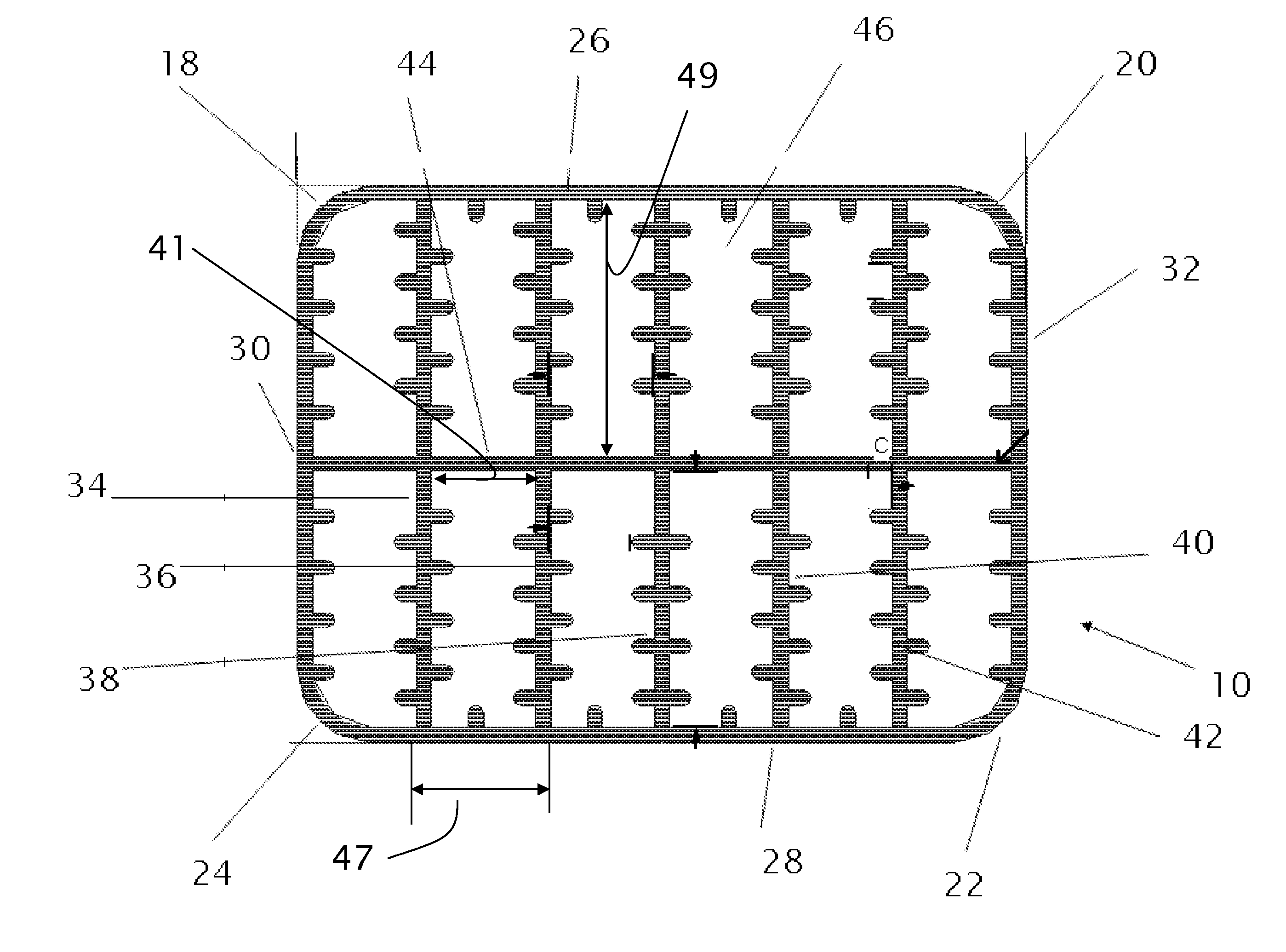
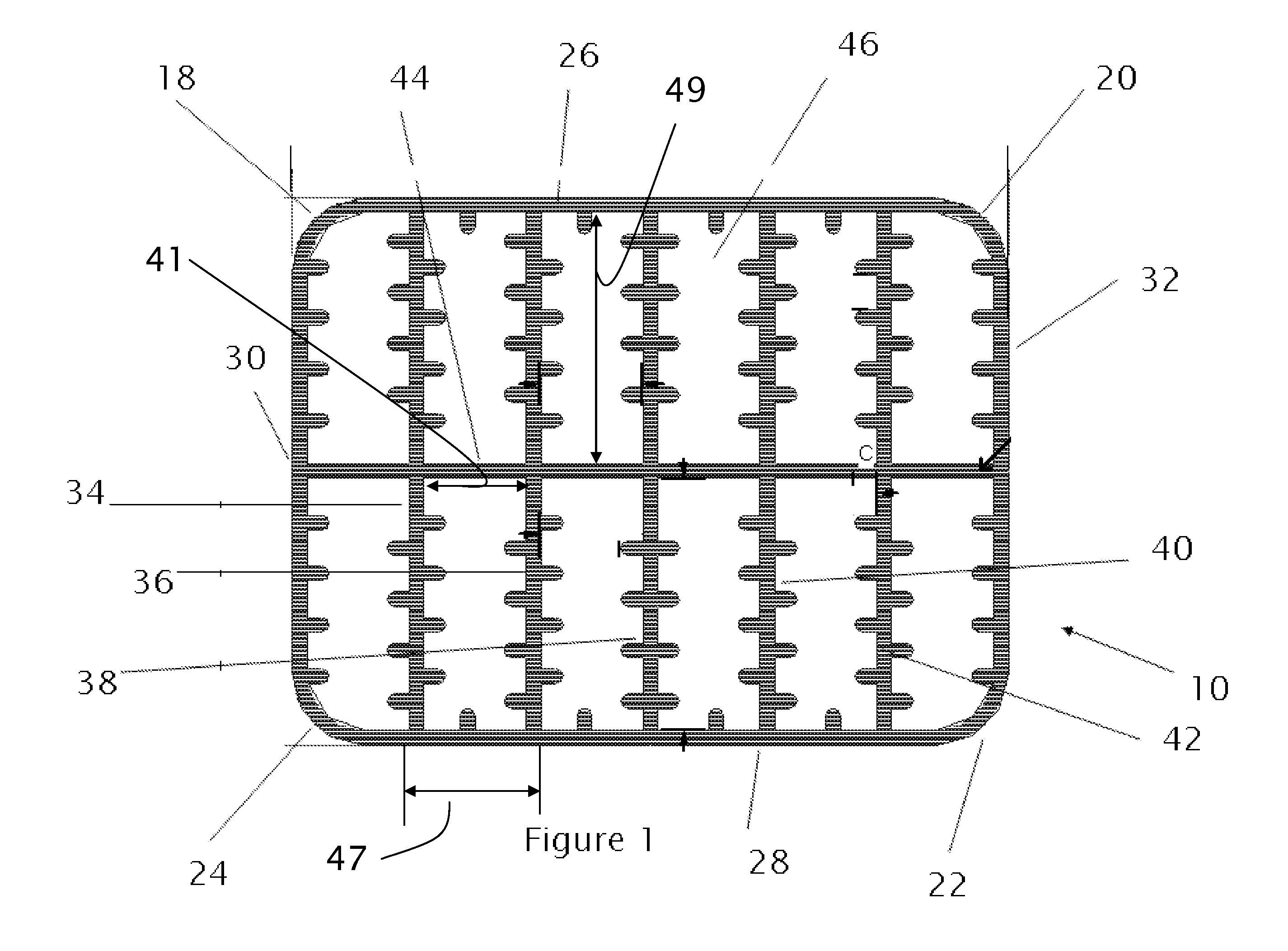
[0027]Referring now to FIG. 1, there is shown the proposed design for my invention (10) depicted in cross section. As illustrated, the biomass carrier (10) of my invention consists of a specific geometric design of the carrier framework.

[0028]Referring now to FIG. 3, there is illustrated the specific morphology for the surfaces (12), (14), and (16) of the biomass carrier illustrated in FIG. 1.

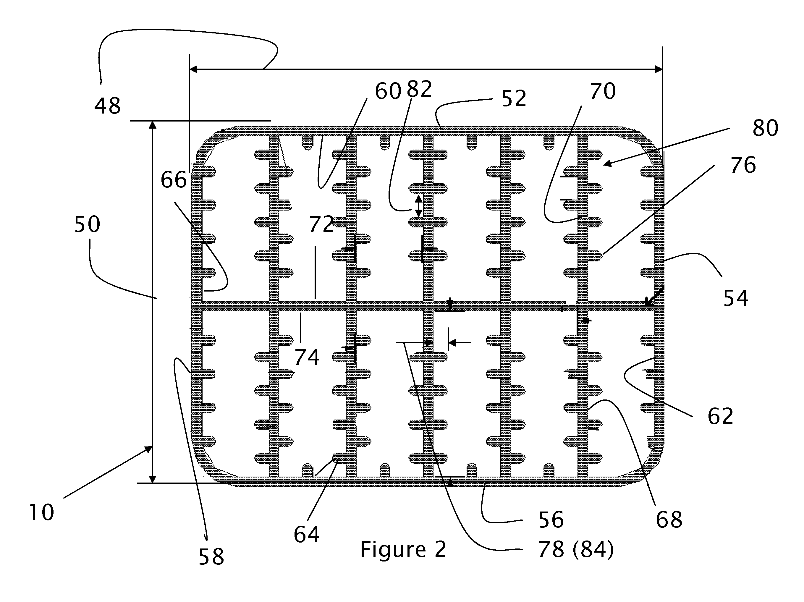
[0029]FIG. 1 depicts the preferred embodiment of the biomass carrier (10) using surface morphology pattern (12). However, the biomass carrier could accommodate any of the alternative patterns (14) or (16) depicted in FIG. 2.

[0030]The profile of the preferred embodiment of the biomass carrier (10) has a substantially hollow rectangular body with rounded corners (18), (20), (22) and (24). For the sake of reference, the biomass carrier comprises four walls: top (26), bottom (28), left (30) and right (32). The body is hollow to permit mass transfer there through. Inside these four walls are equally...


PUM

PropertyMeasurementUnit
aspect ratioaaaaaaaaaa

Abstract

The invention is a biomass carrier used in the biological purification of waste water. The design of the biomass carrier is characterized by a surface morphology designed to produce a specific pattern of variations in bio-film thickness, resulting in optimized bio-film conditions for simultaneous nitrification-de-nitrification and biodegradation of trace organic contaminants.

Description

FIELD OF THE INVENTION[0001]This invention relates to the field of water and wastewater treatment, and particularly to a biomass carrier promoting simultaneous nitrification and de-nitrification of wastewater such as primary and secondary effluents from domestic and industrial wastewater sources.BACKGROUND OF THE INVENTION[0002]As described in pending patent applications such as US2005072732 and US2003127378, various biomass carriers have been designed for use in biological waste water treatment systems. These carriers are contained within a biological reactor vessel and are maintained in a fluidized or constant motion state. Since the biomass carriers are in constant motion, they will collide with each other. Hence the carriers have protected surfaces, typically inside surfaces, that are not exposed to collisions. The reactor vessel receives waste water that may be aerated or oxygenated to support aerobic biological processes useful in the treatment of waste water. The biomass carr...

Claims


Application Information

Patent Timeline
Patent Type & Authority Patents(United States)
IPC IPC(8): C02F3/10
CPCC02F3/10Y10T428/2982Y10S261/72C02F3/302Y02W10/10
Inventor JACKSON, DAVID
Owner JACKSON DAVID
Why Eureka
Try Eureka