Vehicle drive control device

a technology of control device and electric generator, which is applied in the direction of electric energy management, electric devices, gas pressure propulsion mounting, etc., can solve the problems of low rotational speed, ineffective, and increase the size of electric generator and so as to increase the number and/or size of magnets, increase the output of electric generators, and increase the effect of electric generators

a technology of control device and electric generator, which is applied in the direction of electric energy management, electric devices, gas pressure propulsion mounting, etc., can solve the problems of low rotational speed, ineffective, and increase the size of electric generator and so as to increase the number and/or size of magnets, increase the output of electric generators, and increase the effect of electric generators

US7529608B2Inactive Publication Date: 2009-05-05NISSAN MOTOR CO LTD

Image

  • Vehicle drive control device
  • Vehicle drive control device
  • Vehicle drive control device

Examples


Embodiment Construction

[0025]Selected embodiments of the present invention will now be explained with reference to the drawings. It will be apparent to those skilled in the art from this disclosure that the following descriptions of the embodiments of the present invention are provided for illustration only and not for the purpose of limiting the invention as defined by the appended claims and their equivalents.

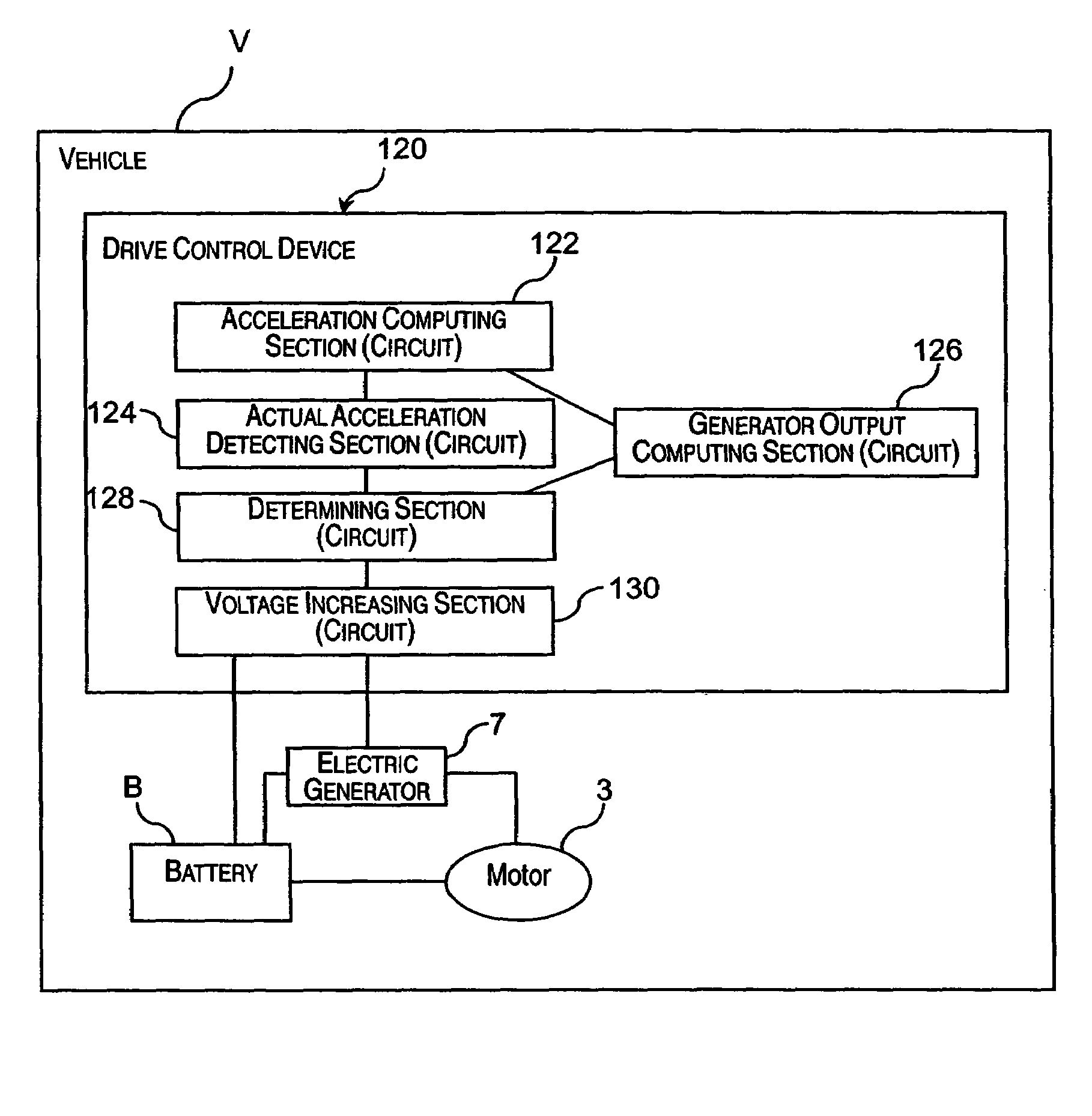
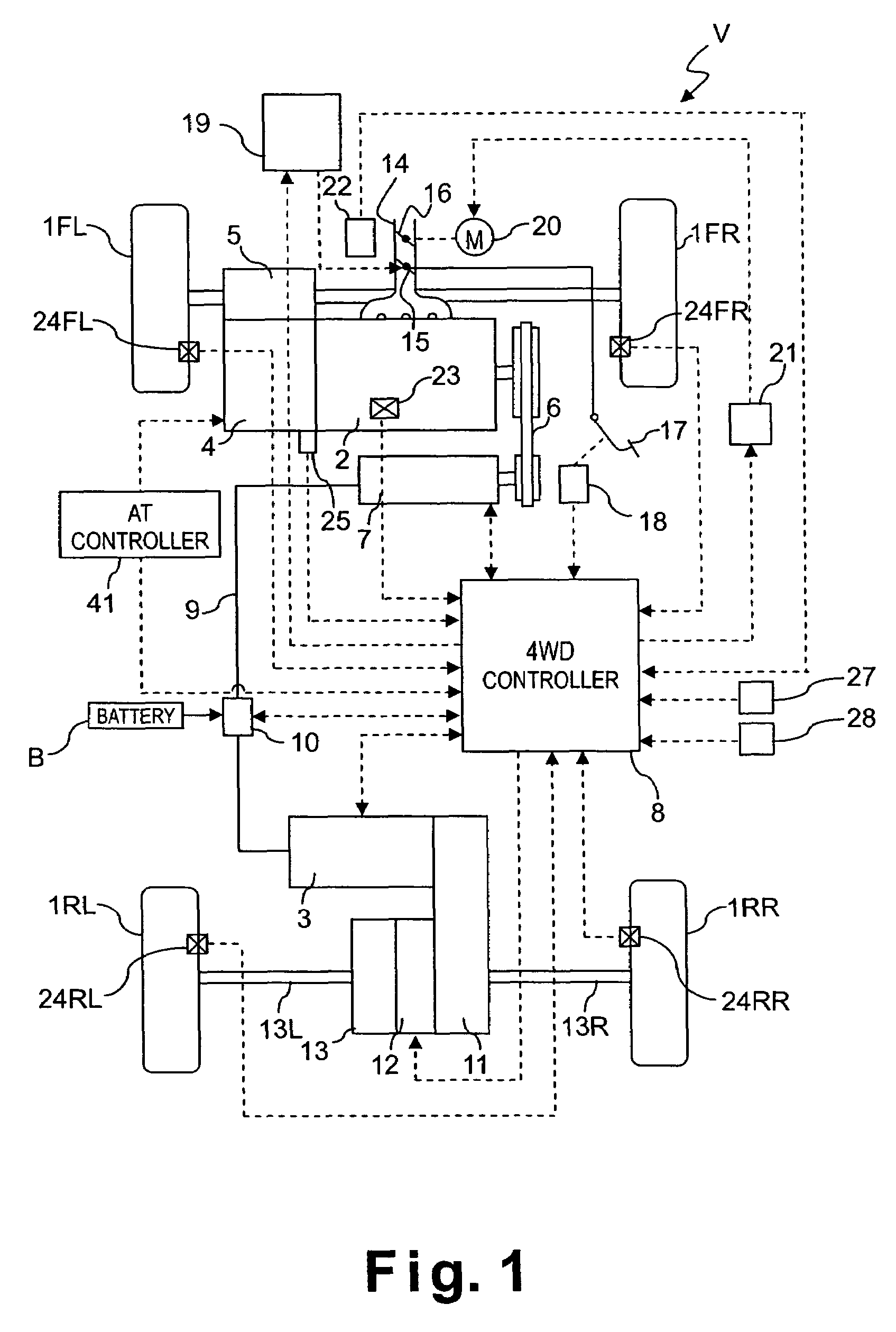
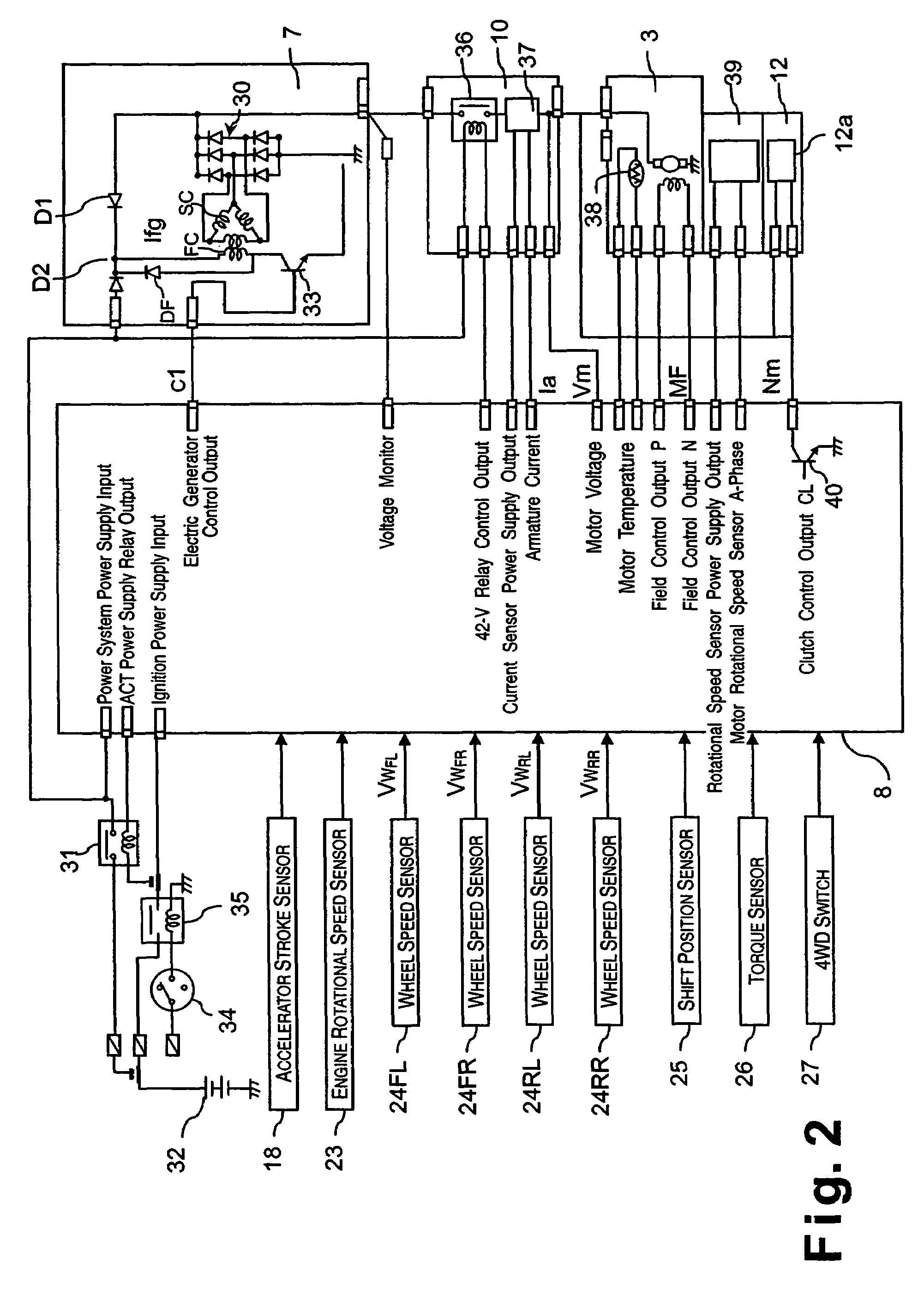
[0026]Referring initially to FIGS. 1 and 2, a vehicle driving force control apparatus will now be explained in accordance with a first embodiment of the present invention. As seen in FIG. 1, a four wheel drive vehicle V is diagrammatically illustrated that is equipped with an electric generator and drive control device in accordance with the present invention. As shown in FIG. 1, the vehicle V in accordance with this embodiment has left and right front wheels 1FL and 1FR that are driven by an internal combustion engine or main drive source 2, and left and right rear wheels 1RL and 1RR that are driv...


PUM


Abstract

A drive control device is provided with a determining section and a voltage increasing section. The determining section determines if the actual acceleration is deficient in comparison with the acceleration requested by the driver or if the generator output is deficient in comparison with the acceleration requested by the driver. The voltage increasing section increases the voltage supplied to the electric generator from a vehicle mounted electric power source when the determining section determines that the actual acceleration or the generator output is deficient. As a result, the generator output deficiency is eliminated and the required motor torque is produced, thereby enabling the vehicle to start into motion appropriately in accordance with the acceleration requested by the driver.

Description

BACKGROUND OF THE INVENTION[0001]1. Field of the Invention[0002]The present invention relates to a vehicle drive control device for a vehicle. More particularly, the present invention relates to a vehicle drive control device provided with an electric generator and a voltage increasing circuit for eliminating generator output deficiencies when they occur.[0003]2. Background Information[0004]In hybrid vehicles driven with both an engine and a motor, the generator output and, thus, the electric power supplied to the motor is often deficient when the rotational speed of the engine is slow, such as when the vehicle is starting into motion from a stopped condition. A typical example is when the vehicle is starting into motion on an upward slope (other examples include starting into motion on a muddy road, a sandy road, or a snowy road) and the electric generator cannot generate sufficient electricity because the engine speed is low. In such a case, the vehicle may not start into motion a...

Claims


Application Information

Patent Timeline
05 May 2009
Publication
US7529608B2
IPC
G06F17/00; B60L11/00; G05F1/10; B60W20/00; B60K6/44; B60K6/52; B60K6/547; B60K17/00; B60L15/20; B60L50/15; B60L50/16; B60W10/08
CPC
B60K6/448; B60L3/10; B60L11/123; B60L15/007; B60L15/20; B60W10/08; B60K6/52; Y02T10/7275
Inventors
SHIMIZU, KOUICHI