Reflective illumination device

a technology of reflecting illumination and illumination device, which is applied in the direction of lighting and heating apparatus, semiconductor devices for light sources, instruments, etc., can solve the problems of severe glare causing discomfort for viewers, limited light angle, damaged leds, etc., and achieve high efficiency

Inactive Publication Date: 2009-05-12
IND TECH RES INST +1
View PDF17 Cites 83 Cited by
  • Summary
  • Abstract
  • Description
  • Claims
  • Application Information

AI Technical Summary

Benefits of technology

[0007]In view of the disadvantages of prior art, the primary object of the present invention is to provide a highly efficient reflective illumination device having a reflecting surface, being the equivalent of a parabolic mirror, in which the direction of the light beams emitted from each light source of the illumination device is adjusted to pour on the reflecting surface by a specific angle so as to be reflected thereby while enabling the illumination device to discharge highly collimated parallel light beams.
[0008]It is another object of the present invention to provide a reflective illumination device with high illuminance.
[0010]It is further another object of the present invention to provide a reflective illumination device capable of preventing glare.

Problems solved by technology

However, as the sizes of these two light sources are considered too large while comparing with that of light emitting diode (LED), LED has been intensely studied and becoming the main trend of future luminaires as the luminous efficiency of LEDs is enhancing continuously and unceasingly.
Since LED is considered to be a flat light source as it can only discharge light beams through the light emitting surface thereof, it can only provide a limited angle of light and thus most LED luminaires are adopting either bottom-lighting module or reflective module.
In addition, as the brightness of a single LED currently available is still not sufficient to be used as the sole and only light source of modern luminaires, a plurality of LEDs are clustered into a lighting module for proving sufficient luminance.
Although the bottom-lighting LED luminaire of FIG. 1 has a plurality of LEDs 14 arranged on a printed circuit board (PCB) 10 that the luminance is enhanced, it is prone to cause severe glare causing discomfort to viewers.
Furthermore, if any individual LED or portion of the plural LEDs is damaged, the damaged LEDs are visible and apparent.
As the result, not only the luminance of the illuminating device is adversely affected, but also no highly collimated parallel light beams can be discharged out of the illuminating device.
Although the forgoing shortcomings can be overcome by improving the design of the reflecting screen 16, it is highly difficult to implement and, in particular, would introduce not much improvement.
Furthermore, since the reflector 44 is inclined, a comparatively large amount of LEDs 12 are required for illuminating similar luminance so that not only the lamp 40 is costly and not power-saving, but also it is bulky and has no surprising appearance.

Method used


Image

  • Reflective illumination device
  • Reflective illumination device
  • Reflective illumination device

Examples


first embodiment

[0049]Please refer to FIG. 5, which is a schematic diagram illustrating a reflective illumination device according to the invention. The illumination device of FIG. 5 is comprised of a light-guiding screen 10, made of a material of light reflecting ability, and at least a light source 20; wherein a light reflecting layer is disposed at the inner wall of the light-guiding screen 10 for increasing the reflectance of the light-guiding screen 10. The light reflecting layer can be a reflective diffusion film, commonly seen in conventional flat panel display, or can be formed by electro-depositing a layer of metal, such as aluminum or electroless nickel, etc. Each light source 20 can be a directional light source capable of emitting light beams by a specific angle, such as light emitting diode (LED). Moreover, the light-guiding screen 10 has a bottom 11 and at least a light-discharging exit 12 formed by the enclosure of a side wall. As seen in FIG. 5, the illumination device is characteri...

third embodiment

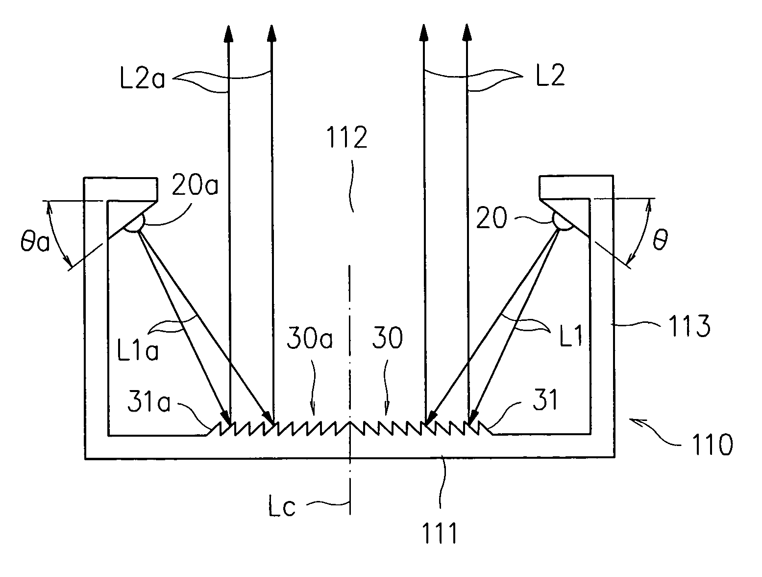
[0054]Please refer to FIG. 7, which a schematic diagram illustrating a reflective illumination device according to the invention. In FIG. 7, the light-guiding screen 210, having a bottom 211 and a light-discharging exit 212, in which the two semi-Fresnel lens structures 30b, 30c and their corresponding light sources 20b, 20c are symmetrically arranged with respect to an axis Lc. The difference between the reflective illumination device of FIG. 7 and that of FIG. 6 is that the two semi-Fresnel lens structures 30b, 30c are respectively arranged on two curved surfaces 214, 215, while the two semi-Fresnel lens structures 30b, 30c are respectively configured with a plurality of ridges 31b, 31c. For matching to the ridges 31b, 31c in respective, the light source 20b, 20c are respectively inclined by an angle θb, θc and disposed at the upper fringe of side wall 213 enclosing the light-discharging exit 212 for enabling the light beams L1b, L1c of the light source to be emitted by a specific...


PUM


Abstract

A reflective illumination device is disclosed, which is comprised of a light-guiding screen with light reflecting ability and at least a directional light source; wherein the light-guiding screen includes a reflecting surface having a semi-Fresnel lens structure arranged thereon. The semi-Fresnel lens structure, being designed basing on the principle of Fresnel lens, is the equivalent of a parabolic mirror that has spiral cut ridges for focusing light to a focal point, whereas the profile of the ridges can be a planar surface, a curved surface or the combination thereof. By arranging the reflecting surface with semi-Fresnel lens structure at the bottom of the light-guiding screen and each light source at a circumferential side wall of the light-guiding screen, the light beams emitting from each light source can be reflected out of the light-guiding screen by a specific angle as the direction of the light beams is adjusted to pour on the semi-Fresnel lens structure by a specific angle matching the configuration of the same.

Description

FIELD OF THE INVENTION[0001]The present invention relates to a reflective illumination device, and more particularly, to a highly efficient illumination device having a reflecting surface with semi-Fresnel lens structure, being designed basing on the principle of Fresnel lens and being the equivalent of a parabolic mirror, in which the direction of the light beams emitted from each light source of the illumination device is adjusted to pour on the semi-Fresnel lens structure by a specific angle so as to be reflected thereby while enabling the illumination device to discharge highly collimated parallel light beams.BACKGROUND OF THE INVENTION[0002]Generally, the light sources of conventional luminaires usually can be sorted into two categories, which are point sources such as incandescent bulb and energy-saving fluorescent bulb, and line source such as fluorescent tube. These two types of light source are all capable of discharging light beams in a radiation manner. However, as the si...

Claims


Application Information

Patent Timeline
Patent Type & Authority Patents(United States)
IPC IPC(8): F21V7/00
CPCF21S4/003F21V7/0008F21V7/09F21Y2101/02F21Y2103/003F21Y2103/022G02B3/08F21S4/20F21Y2103/10F21Y2115/10F21Y2103/33
Inventor LIN, JIAN-SHIANWANG, JIAN-CHIUANLAI, CHIEH-LUNGHSU, HSIU-CHENSUN, YI-TING
Owner IND TECH RES INST
Why Eureka
Try Eureka