High-frequency connector assembly

Active Publication Date: 2009-05-12
LIH YEU SENG IND
View PDF3 Cites 10 Cited by
  • Summary
  • Abstract
  • Description
  • Claims
  • Application Information

AI Technical Summary

Benefits of technology

[0007]The present invention is thus provided to improve all existing problems related to connectors for various communication devices and propose a high-frequency

Problems solved by technology

Consequently, after a period of use, the components in the assembled connecting members may suffer from oxidation and rustiness, and degeneration of transmission efficiency of the connecting members may therefore occur.
Besides, when the slit 101 of the terminal block 10 can only provide the resili

Method used


Image

  • High-frequency connector assembly
  • High-frequency connector assembly
  • High-frequency connector assembly

Examples


Example

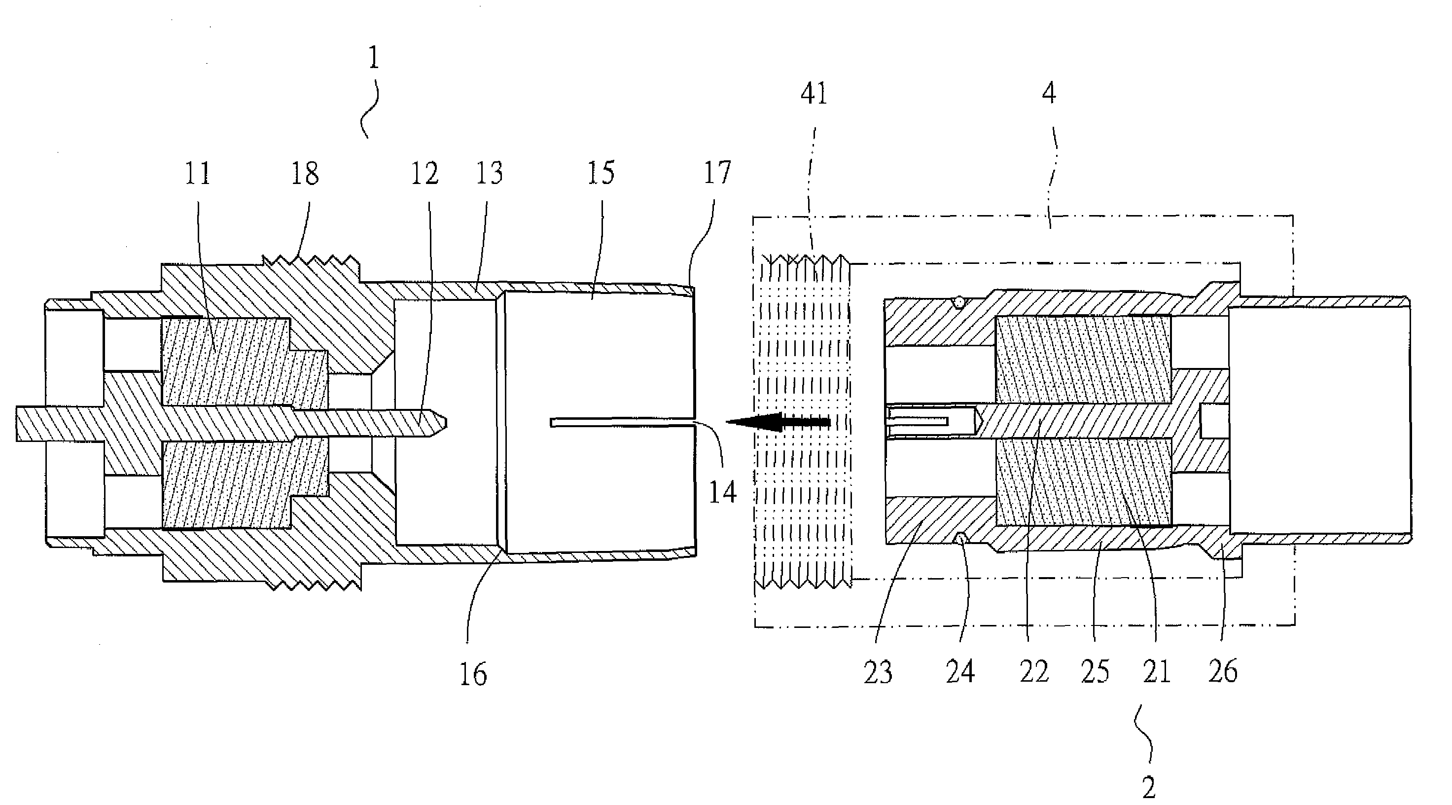
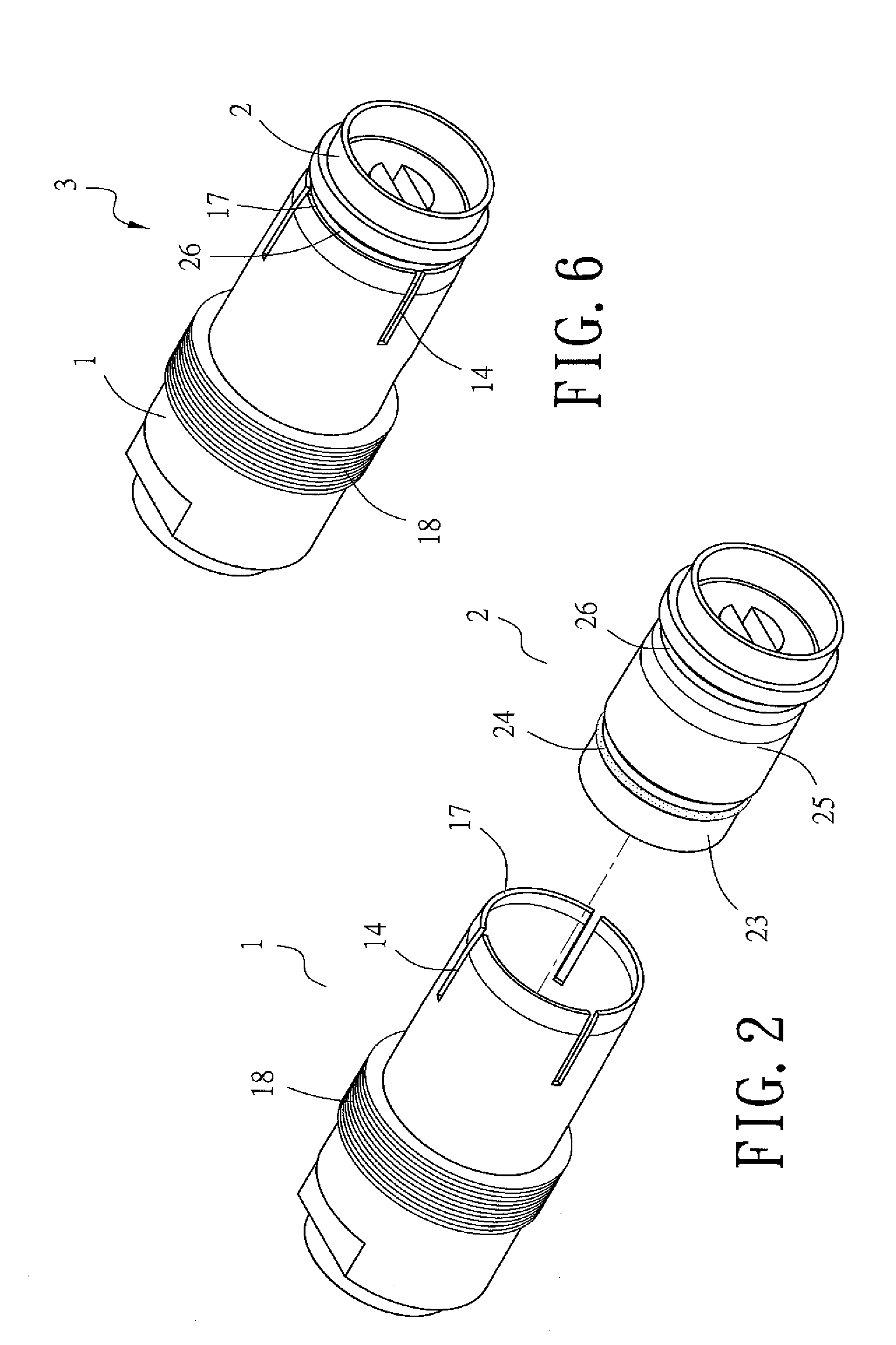
[0031]Please refer to FIGS. 2 and 3 for a high-frequency connector assembly of the present invention. Therein, a first connector 1 and a second connector 2 are assembled to form the high-frequency connector assembly 3.

[0032]The first connector 1 inside is formed with an anti-slip annular section 131 (embodied by inner threads formed along a positive direction and a negative direction according to the present embodiment) for fittingly settling an insulator 11 therein so as to position a conductive pin 12 in the first connector 1. The first connector 1 is further formed with at least one slit 14 at a receiving periphery 13 on a working end thereof. An expanded section 15 having an expanded diameter inside of the first connector 1 faces an opening of the working end. A transitional rim 16 is defined between inner surfaces of the expanded section 15 and the receiving periphery 13. In addition, a contracted edge 17 having one slope is formed at an end of the expanded section. A threaded ...


PUM


Abstract

A high-frequency connector assembly includes a first connector having a conductive pin and formed with at least one slit at a receiving periphery thereof for allowing a second connector inlaid with an O-ring to be inserted therein. The pin in the first connecter can be received by a pin holder in the second connector. An expanded section at a rear portion of the second connector is received by an expanded section of the first connector. An annular groove formed adjacent to the expanded section on the second connector pressingly abuts against a contracted edge slope at an end of the receiving periphery of the first connector. The connector assembly facilitates mitigating attrition caused by frequent vibration and provides a damp-proof effect, thereby ensuring a desired transmission efficiency.

Description

BACKGROUND OF THE INVENTION[0001]1. Technical Field[0002]The present invention relates to a connector assembly applied to communication devices used under highly vibrational operating conditions, such as mobile phones, aircraft or vehicle communication devices, etc., wherein the connector assembly ensures desired transmission efficiency by suppressing external interference and providing a damp-proof effect.[0003]2. Description of Related Art[0004]While various connectors serving diverse communication devices have been developed, a conventional approach for providing two assembled connecting members (as shown in FIG. 1) with a spring clamping connection therebetween involves inserting a terminal block 10, that is embracing a conductive pin 20 and that is formed with a slit 101 at an outer periphery thereof into a receiving hole 301 provided on a matching terminal block 30. Thus, the outer periphery 102 of the terminal block 10 can resiliently press against an annular groove 302 forme...

Claims


Application Information

Patent Timeline
IPC IPC(8): H01R9/05
CPCH01R9/0521H01R13/5219H01R13/533H01R13/6277
Inventor HSU, CHIN-TENG
Owner LIH YEU SENG IND
Why Eureka
Try Eureka