Actively driven spiral pipeline robot

Inactive Publication Date: 2015-10-22
SOUTHWEST PETROLEUM UNIV
View PDF4 Cites 13 Cited by
  • Summary
  • Abstract
  • Description
  • Claims
  • Application Information

AI Technical Summary

Benefits of technology

[0016]The present invention has following advantages: the driving wheel is directly driven to rotate by the driving device so that a rotation speed of the driving wheel is not restricted by an included angle between an axis of rotation of the driving wheel and the axis of the body, a scope of application of the robot is expanded, a transmission efficiency is high, an operation

Problems solved by technology

The poor work environment of these pipeline systems usually causes corrosion or fatigue failure to the pipes or makes potential internal pipeline faults develop into breakages, thus leading to leakage accidents.
However, the operator cannot directly arrive at or be involved into the pipeline because of the local environment or the size limitation of the pipeline, thus, it is difficulty to maintain the pipeline.
A pressure peristaltic inchworm type caterpillar device developed by Tokyo Institute of Technology has a slow speed and a complex control system.
Such structure has disadvantages of great energy loss and non-reliable transmission movement.
However, the spiral angle of the spiral trail is

Method used


Image

  • Actively driven spiral pipeline robot
  • Actively driven spiral pipeline robot
  • Actively driven spiral pipeline robot

Examples


Example

Embodiment 1

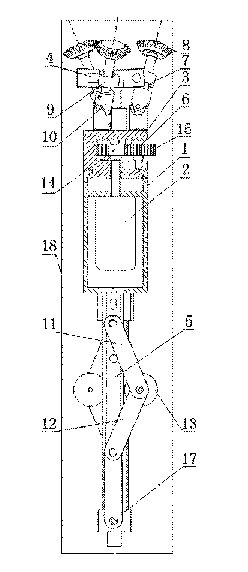
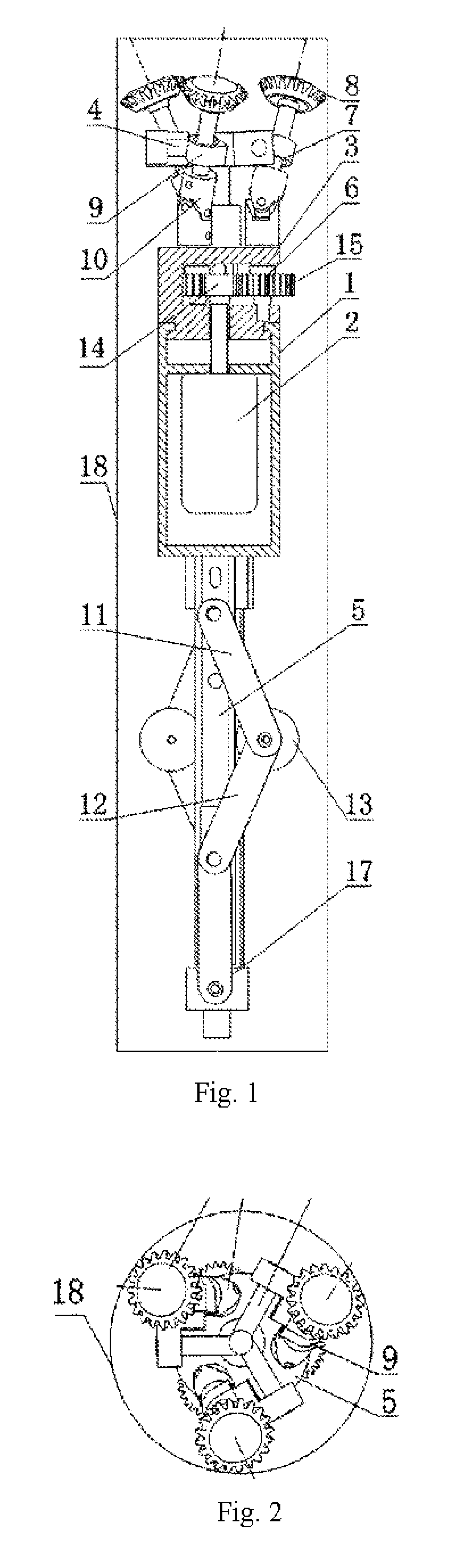
[0031]As shown in FIG. 1 and FIG. 2, an actively driven spiral pipeline robot comprises a driving wheel carrier 3, a body 1, a guide wheel carrier 5 and a power device 2. The power device 2 is fixedly disposed in the body 1. The driving wheel carrier 3 is rotatablely mounted at one end of the body 1. The guide wheel carrier 5 is fixedly disposed at the other end of the body 1. Three variable diameter mechanisms are uniformly distributed along a circumferential direction of the guide wheel carrier 4, that is, two adjacent variable diameter mechanisms 4 are in an angle of 120°. A driving shaft 6 and an axle 7 are further disposed on the driving wheel carrier 3. A driving wheel 8 is fixedly mounted at one end of the axle 7. An axis of rotation of the driving wheel 8 coincides with an axis of the axle 7. A bearing saddle 9 is disposed on each variable diameter mechanism 4. The axle 7 is mounted in the bearing saddle 9 via a bearing. The driving shaft 6 is mounted on the driv...

Example

Embodiment 2

[0035]As shown in FIG. 5, an actively driven spiral pipeline robot comprises a driving wheel carrier 3, a body 1, a guide wheel carrier 5 and a power device 2. The power device 2 is fixedly disposed in the body 1. The driving wheel carrier 3 is rotatablely mounted at one end of the body 1. The guide wheel carrier 5 is fixedly disposed at the other end of the body 1. One variable diameter mechanism 4 is disposed on the driving wheel carrier 3. A driving shaft 6 and an axle 7 are further disposed on the driving wheel carrier 3. A driving wheel 8 is fixedly mounted at one end of the axle 7. An axis of rotation of the driving wheel 8 coincides with an axis of the axle 7. A bearing saddle 9 is disposed on the variable diameter mechanism 4. The axle 7 is mounted in the bearing saddle 9 via a bearing. The driving shaft 6 is mounted on the driving wheel carrier 3 via a bearing. The driving shaft 6 and the axle 7 are connected via a connector W that is a Cardan joint. The driving...

Example

Embodiment 3

[0039]As shown in FIG. 9, an actively driven spiral pipeline robot comprises a driving wheel carrier 3, a body 1, a guide wheel carrier 5 and a power device 2. The power device 2 is fixedly disposed in the body 1. The driving wheel carrier 3 is rotatablely mounted at one end of the body 1. The guide wheel carrier 5 is fixedly disposed at the other end of the body 1. Two variable diameter mechanisms are uniformly distributed along a circumferential direction of the guide wheel carrier 4, that is, two adjacent variable diameter mechanisms 4 are in an angle of 180°. A driving shaft 6 and an axle 7 are further disposed on the driving wheel carrier 3. A driving wheel 8 is fixedly mounted at one end of the axle 7. An axis of rotation of the driving wheel 8 coincides with an axis of the axle 7. A bearing saddle 9 is disposed on each variable diameter mechanism 4. The axle 7 is mounted in the bearing saddle 9 via a bearing. The driving shafts 6 are mounted on the driving wheel c...


PUM


Abstract

An actively driven spiral pipeline robot is disclosed, comprising: a body, a power device, a driving shaft, an axle, a driving wheel carrier mounted at one end of the body, and a variable diameter mechanism disposed on the driving wheel carrier. The axle is disposed on the variable diameter mechanism. A driving wheel is fixedly mounted on the axle. The driving shaft and the axle are connected via a connector. The driving shaft is further connected with an output shaft of the power device via a transmission device. The present invention has following beneficial effects: a scope of application of the robot is expanded, an operation is stable, and an axial force is large. In addition, an axial position of the robot is adjusted by controlling an operation of the driving wheel, and an adjustment precision is high.

Description

TECHNICAL FIELD[0001]The present invention relates to a robot walking in a pipeline, and in particular, to an actively driven spiral pipeline robot.BACKGROUND ART[0002]At present, the pipeline robot is a new technology rising in recent years and combining fields of precision machinery, robotics, new material and control theory. A great many micro pipelines, such as heat transfer pipes for steam generators in nuclear power plant and industrial pipes and gas pipes in fields of metallurgy, oil, chemical, city heating supply and refrigeration, are used in modern industrial and agricultural productions and daily life. The poor work environment of these pipeline systems usually causes corrosion or fatigue failure to the pipes or makes potential internal pipeline faults develop into breakages, thus leading to leakage accidents. Therefore, the monitoring, diagnosis, clearing and maintenance of the pipelines has become the key to guarantee the security, smooth and efficient operation of the ...

Claims


Application Information

Patent Timeline
IPC IPC(8): F16L55/32
CPCF16L55/32
Inventor LIU, QINGYOUREN, TAOCHEN, YONGHUA
Owner SOUTHWEST PETROLEUM UNIV
Why Eureka
Try Eureka