Wavelength division multiplexing optical transmission system

Inactive Publication Date: 2005-06-09
FUJITSU LTD
View PDF4 Cites 4 Cited by
  • Summary
  • Abstract
  • Description
  • Claims
  • Application Information

AI Technical Summary

Benefits of technology

[0020] The employment of the above-mentioned st

Problems solved by technology

However, this covers only 80% of a transmission block region in a metro area network.
In general, the cost of the wavelengt

Method used


Image

  • Wavelength division multiplexing optical transmission system
  • Wavelength division multiplexing optical transmission system
  • Wavelength division multiplexing optical transmission system

Examples


Embodiment Construction

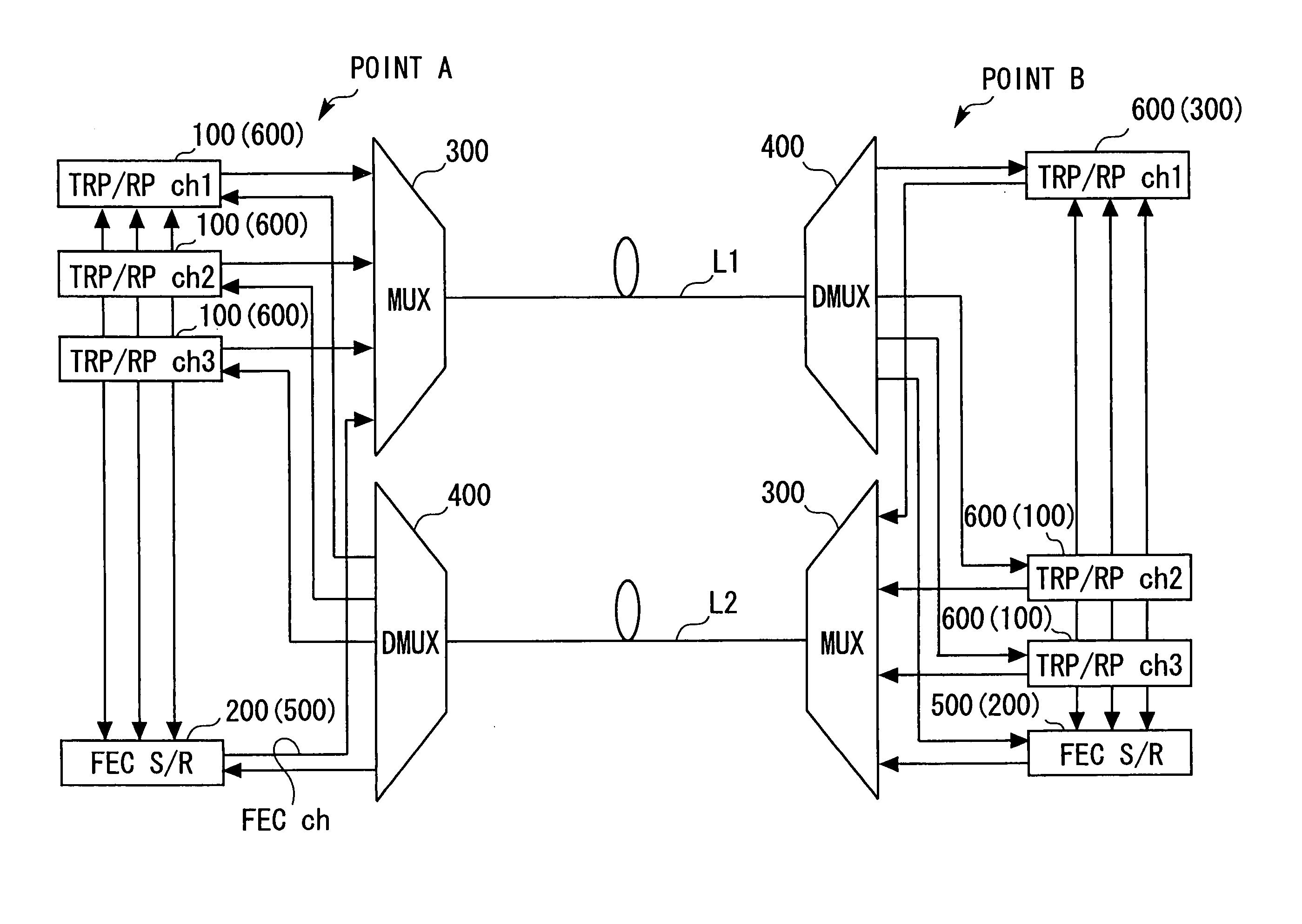
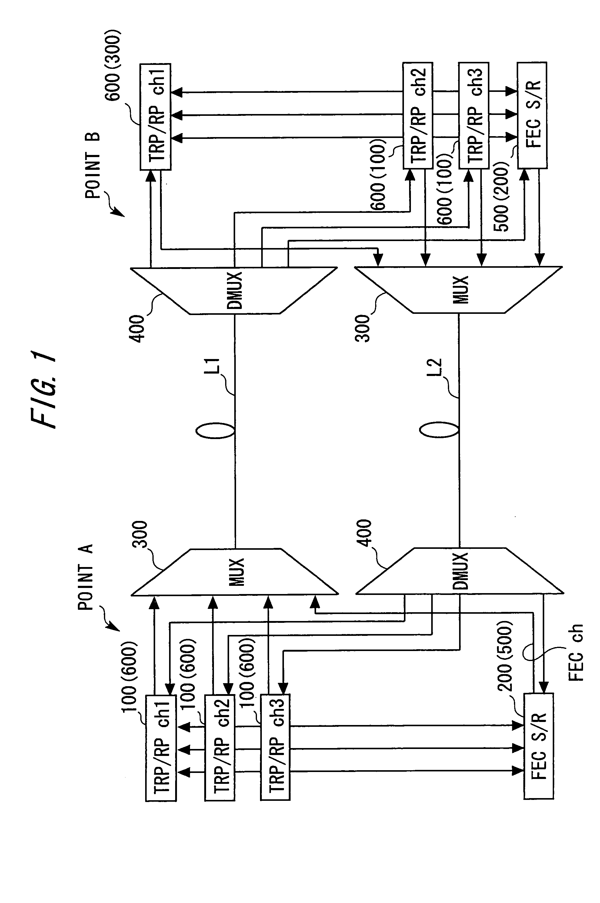
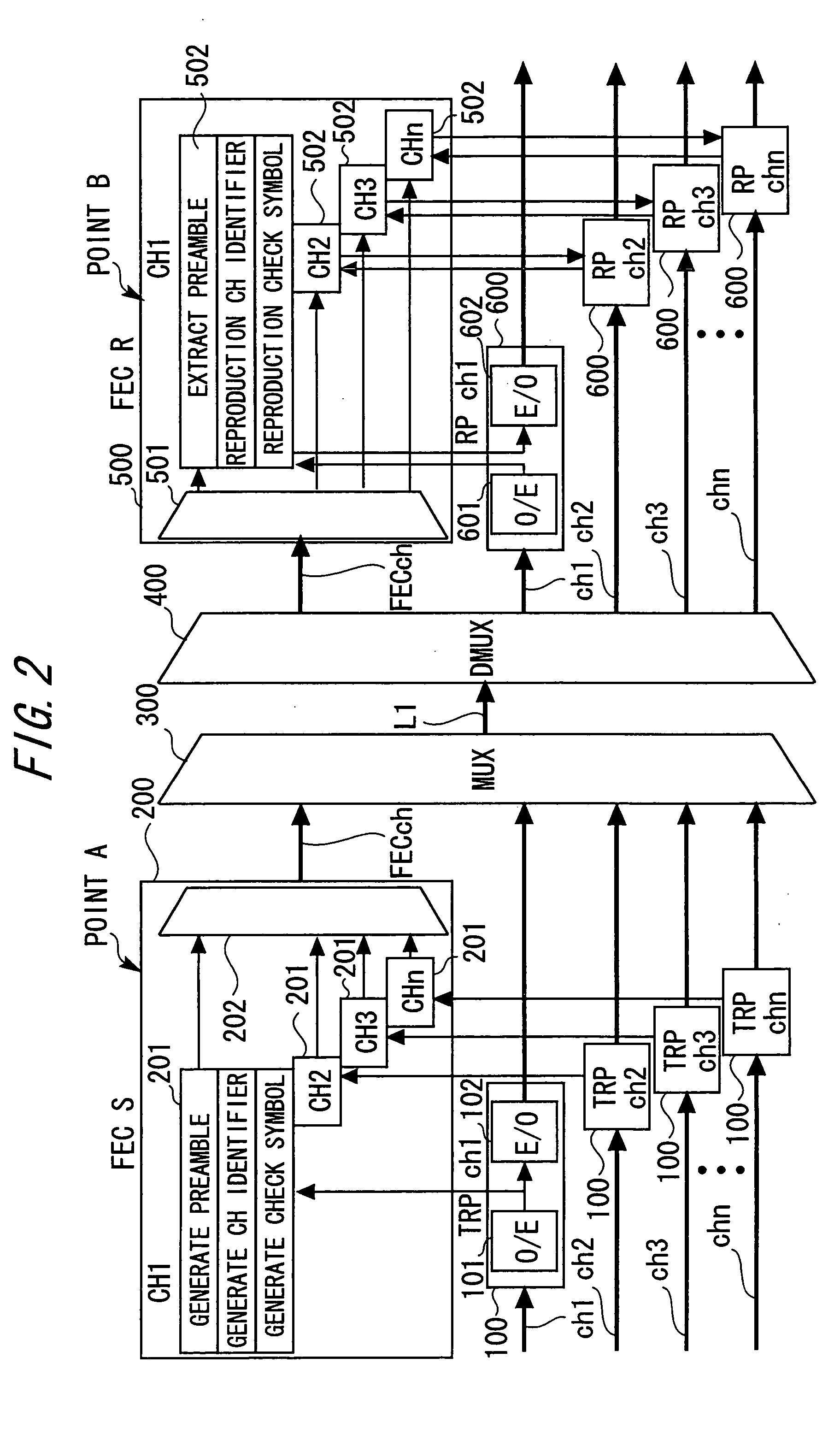
[0028] A wavelength division multiplexing optical transmission system according to an embodiment of the present invention will be described below with reference to the drawings. FIG. 1 is a diagram explaining the schematic system configuration of the wavelength division multiplexing optical transmission system according to the embodiment of the present invention.

[0029] The wavelength division multiplexing optical transmission system includes a plurality of transmission transponders 100, an FECS 200, a multiplexer 300, an isolator 400, an FECR 500 and a plurality of reception transponders 600, for each of points (for example, a point A and a point B).

[0030] The multiplexer 300 of a certain point (for example, the point A) and the isolator 400 of another point (for example, the point B) are connected through an optical transmission path L1 (refer to the upper stage of FIG. 1). Similarly, the isolator 400 of the certain point (for example, the point A) and the multiplexer 300 of the ...


PUM


Abstract

A wavelength division multiplexing optical transmission system for multiplexing a plurality of optical signals of the wavelength different from each other. The system comprises a first converter converting the plurality of optical signals whose wavelengths are different from each other, into a plurality of electric signals, a generator generating check symbols for the plurality of electric signals input from the first converter, a second converter converting the check symbols input from the generator, into optical signals whose wavelengths are different from the plurality of optical signals, a multiplexer multiplexing and sending out the plurality of optical signals and the optical signals input from the second converter, and an isolator isolating the multiplexed optical signal input from the multiplexer.

Description

BACKGROUND OF THE INVENTION [0001] The present invention relates to a technology that enables a long distance transmission at a low cost in a wavelength division multiplexing optical transmission system. [0002]FIG. 7 shows a schematic system configuration of a conventional wavelength division multiplexing optical transmission system. TRP / RP is a transmission / reception transponder, MUX is an optical multiplexer, DMUX is an optical isolator, and OFA is an optical amplifier. In this conventional wavelength division multiplexing optical transmission system, a signal is converted into a narrow band optical wavelength signal by the transmission transponder TRP, wavelength division multiplexed (WDM) by the optical multiplexer MUX, and optically amplified by a transmission optical amplifier of the optical amplifier OFA, and then sent out to an optical transmission path. On the other hand, an optical signal attenuated in the optical transmission path is amplified by a reception optical ampli...

Claims


Application Information

Patent Timeline
IPC IPC(8): H04J14/02
CPCH04J14/02
Inventor SAKATA, TAKASHISASAKI, KENICHI
Owner FUJITSU LTD
Why Eureka
Try Eureka