

Wireless power transfer device and method with dual-frequency operation
- Summary
- Abstract
- Description
- Claims
- Application Information
AI Technical Summary
Benefits of technology
Problems solved by technology
Method used
Image

Examples
experimental conclusions
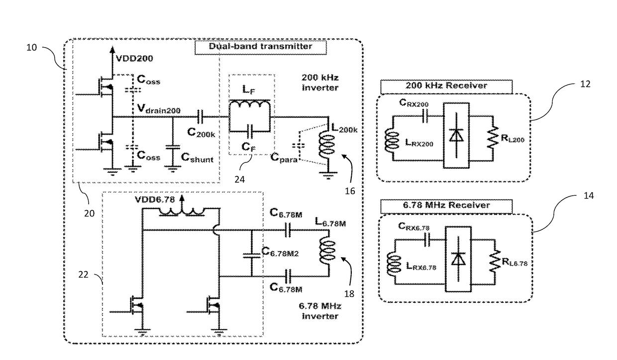
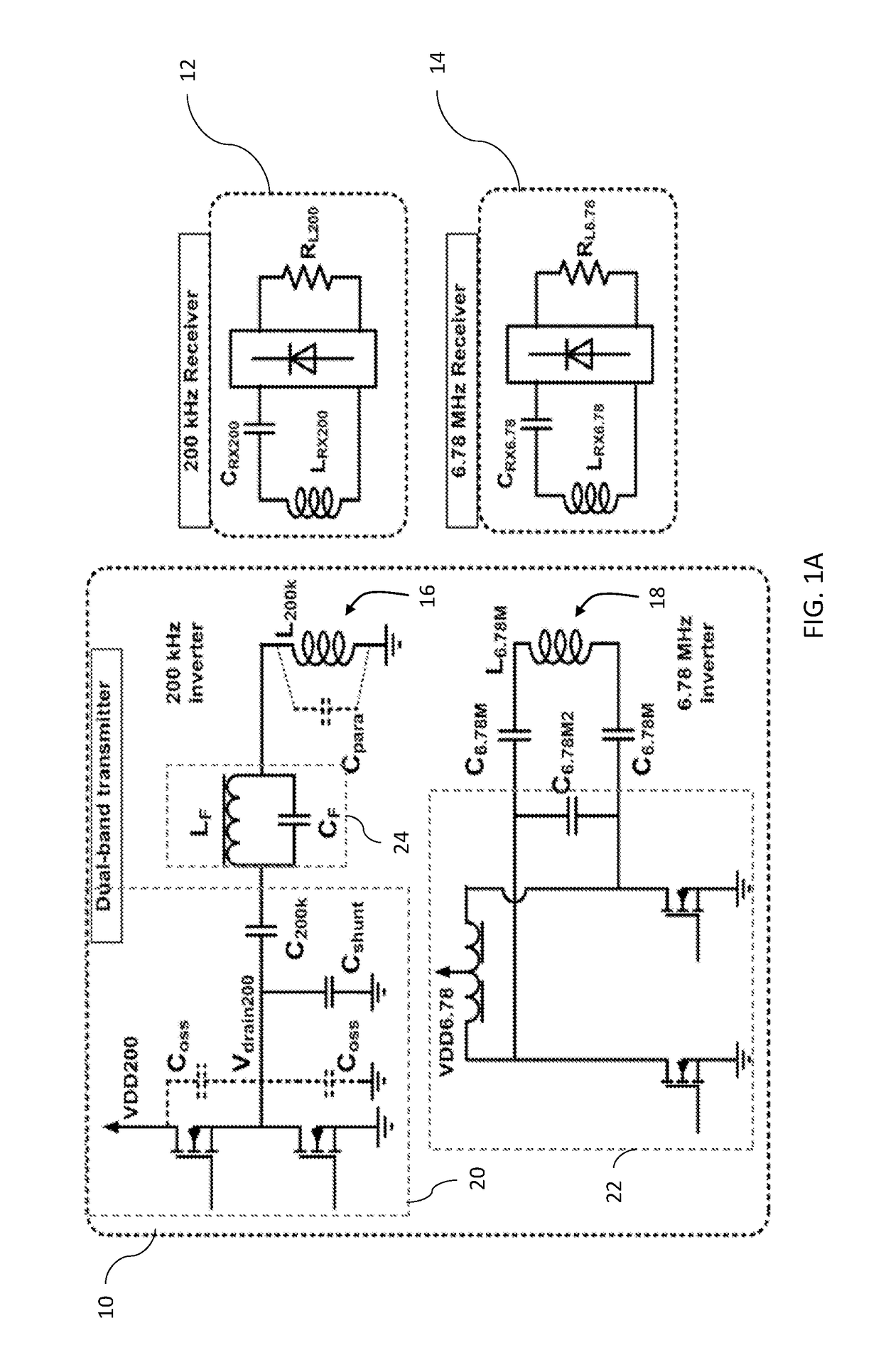
[0090]The experimental embodiments demonstrated a dual-frequency wireless power transfer transmitter module that can simultaneously power two receivers operating at either 200 kHz, which is in the range of the WPC / PMA standards, or 6.78 MHz, which is supported by the A4WP standard. Achieving dual-band support, especially when the desired frequencies are an order of magnitude apart, requires careful consideration of parasitics, coil design, and eddy current paths. In particular, the lower frequency path should include impedance that is at least four times higher for the higher frequency than experienced by the lower frequency.
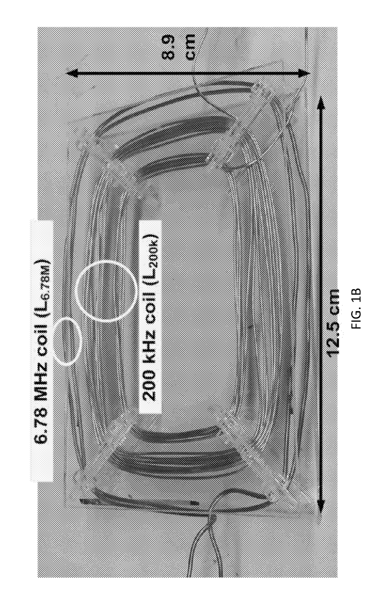
[0091]The preferred experimental embodiment in accordance with FIGS. 1A and 1B provided a practical two-coil, dual-band power transmitting device that enables concurrent operation. Analytical expressions predicting the eddy current losses associated with the two-coil system are provided in this application will enable artisans to apply the general principles of ...
PUM
 Abstract
Description
Claims
Application Information