Lateral-flow biohazard safety enclosure

a biohazard and safety enclosure technology, applied in the field of laboratory safety enclosures, to achieve the effect of facilitating cleaning and replacement, facilitating operator access, and avoiding fan contamination

Inactive Publication Date: 2009-05-12
FLOW SCI INC
View PDF26 Cites 8 Cited by
  • Summary
  • Abstract
  • Description
  • Claims
  • Application Information

AI Technical Summary

Benefits of technology

[0018]It has been found that the present configuration provides significant advantages over prior art vented workstations. A larger chamber is available, permitting the enclosure of automated instruments used to manipulate biological materials; laminar airflow through the chamber is possible; and ease of operator access into the chamber is provided. By positioning a HEPA filter between the air outlet opening and the fan, contamination of the fan is avoided, facilitating cleaning and replacement, if needed.

Problems solved by technology

However, many laboratory and manufacturing procedures now require isolation from the environment of automated instrumentation that is simply too large to conveniently fit within a conventionally designed workstation, while still achieving the desired non-turbulent airflow.

Method used


Image

  • Lateral-flow biohazard safety enclosure
  • Lateral-flow biohazard safety enclosure
  • Lateral-flow biohazard safety enclosure

Examples


Embodiment Construction

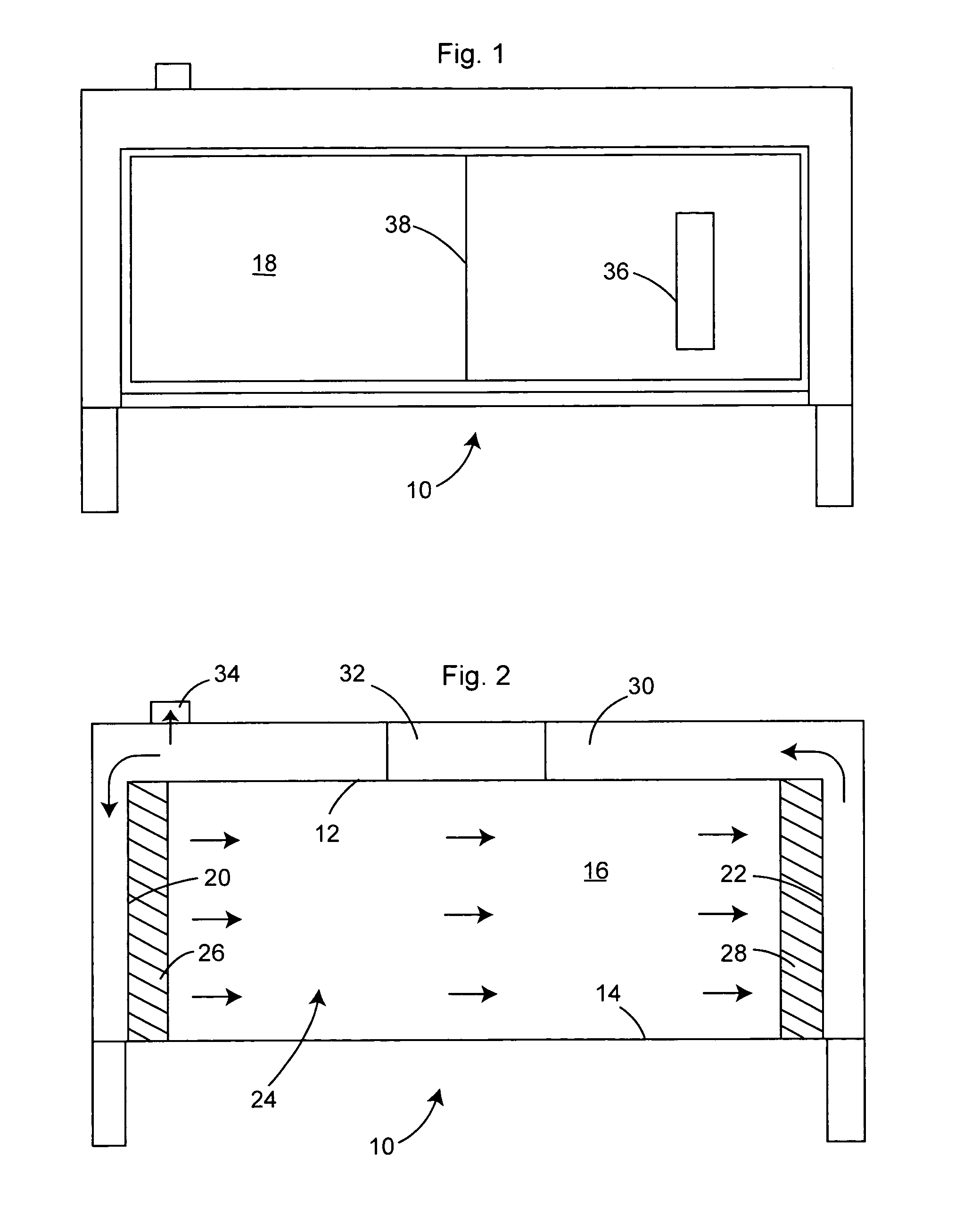
[0027]FIGS. 1 and 2 illustrate a preferred workstation, generally 10, comprised of a top wall 12, bottom wall 14, back wall 16, front wall 18, first end wall 20 and opposite second end wall 22. The walls together form a work chamber 24. Non-loading HEPA filter 26 is positioned across end wall 20, while a loading HEPA filter 28 is positioned across end wall 22. Conduit 30 extends between the exterior of the filters, with fan 32 being positioned to draw air from chamber 24 through HEPA filter 28 and into chamber 24 through non-loading HEPA filter 26. Conduit 30 includes an exhaust port 34 downstream of fan 32 to discharge air from workstation 10. Inlet 36 into chamber 24 is provided for introduction of make-up air. Closeable inlet 38 is also provided for access to chamber 24.

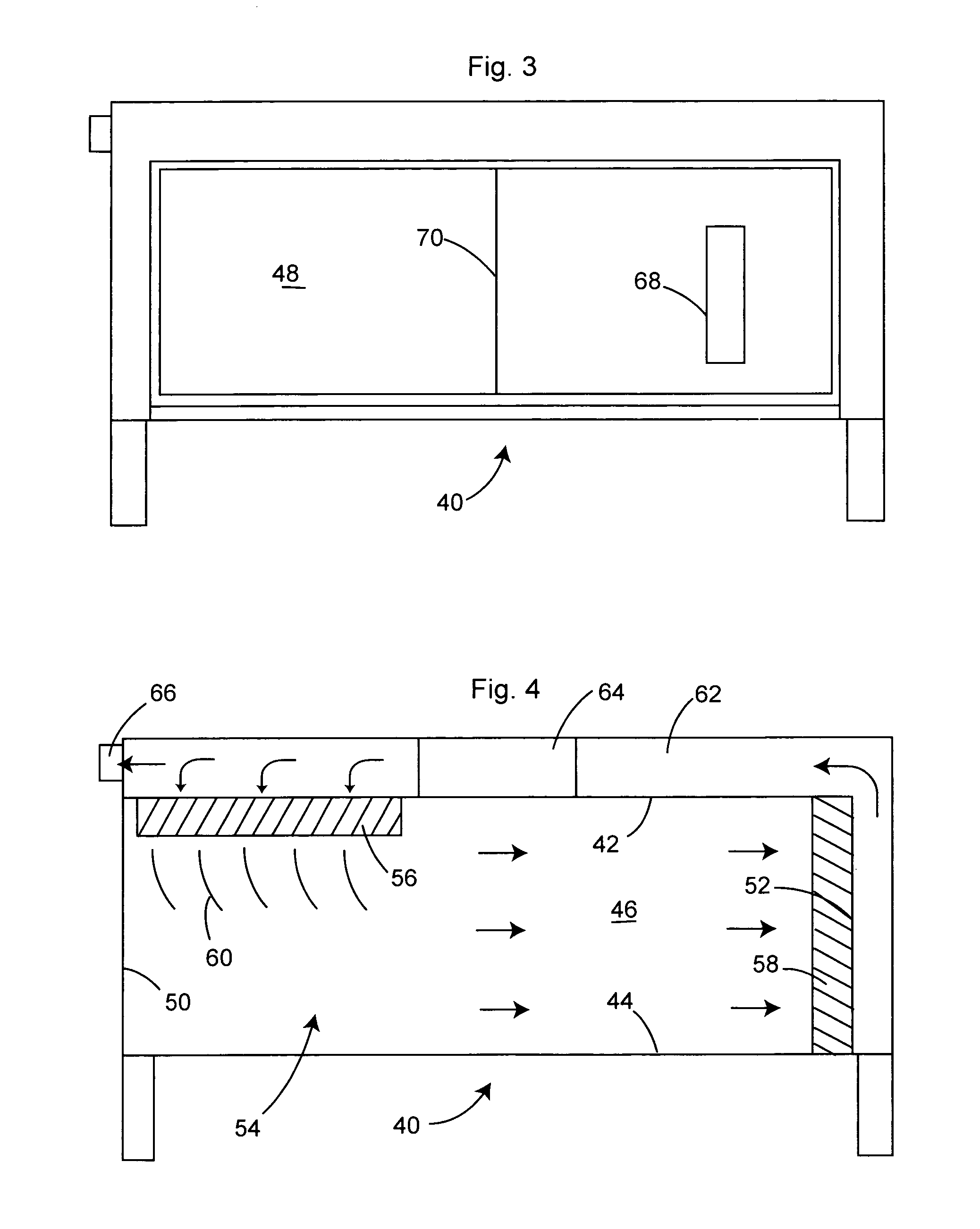
[0028]A second embodiment of the invention, generally 40, illustrated in FIGS. 3 and 4, is comprised of top wall 42, bottom wall 44, back wall 46, front wall 48, first end wall 50 and opposite second end wall 52. ...


PUM

PropertyMeasurementUnit
surface areaaaaaaaaaaa
cross-sectional areasaaaaaaaaaa
areaaaaaaaaaaa

Abstract

A biohazard safety enclosure or workstation particularly adapted for enclosing automated instrumentation includes a chamber defined by front, back, top, bottom, and opposed end walls; a HEPA filter across an air inlet opening into the chamber, and an airflow means to direct air horizontally through at least part of the chamber between the end walls. Preferably, the workstation has a second HEPA filter across an air outlet opening in the work chamber, with the airflow means including a conduit extending from the air outlet opening to the air inlet opening. A fan draws air through the conduit. All of the air can be exhausted from the workstation, or a part of the filtered air can be exhausted from the workstation and replenished through a make-up air inlet into the chamber.

Description

[0001]This application is a continuation-in-part of U.S. patent application Ser. No. 10 / 628,179, filed Jul. 28, 2003 now U.S. Pat. No. 6,896,712.BACKGROUND OF THE INVENTION[0002]1. Field of the Invention[0003]The present invention relates to laboratory safety enclosures for use in handling biohazard materials, and in particular to laboratory safety enclosures for use in housing automated instrumentation used in the handling of biohazard materials.[0004]2. Description of the Prior Art[0005]Laboratory safety enclosures, also known as vented workstations, are safety devices used in research, analytical, teaching, and other laboratories. These containment devices provide enclosed work areas where handling of toxic substances can be performed with minimum risk to users. They are used primarily in pharmaceutical, chemical, biological and toxicological laboratory settings.[0006]Specifically, a laboratory safety enclosure is comprised of a work chamber within which materials are manipulated...

Claims


Application Information

Patent Timeline
Patent Type & Authority Patents(United States)
IPC IPC(8): B01D50/00B01L1/00B08B15/02F24F3/16
CPCB01L1/50B08B15/023F24F3/1607F24F3/163Y10S55/18
Inventor RYAN, RAYMOND F.MCNALLY, JOHN H.
Owner FLOW SCI INC
Why Eureka
Try Eureka