Comb filter system and method

a comb filter and video signal technology, applied in the field of image processing, can solve the problems of limiting the use of composite video signals, affecting the quality of displayed video pictures, and complicating the development of multi-standard 3d comb filters

Active Publication Date: 2009-05-12
PIXELWORKS SEMICON TECH SHANGHAI CO LTD
View PDF57 Cites 22 Cited by
  • Summary
  • Abstract
  • Description
  • Claims
  • Application Information

AI Technical Summary

Problems solved by technology

The Y / C crosstalk generally degrades the quality of displayed video pictures.
Previous 3D comb filtering, however, has been confined to Y / C separation, which limits its use to composite video signals and complicates the development of a multi-standard 3D comb filter.

Method used


Image

  • Comb filter system and method
  • Comb filter system and method
  • Comb filter system and method

Examples


Embodiment Construction

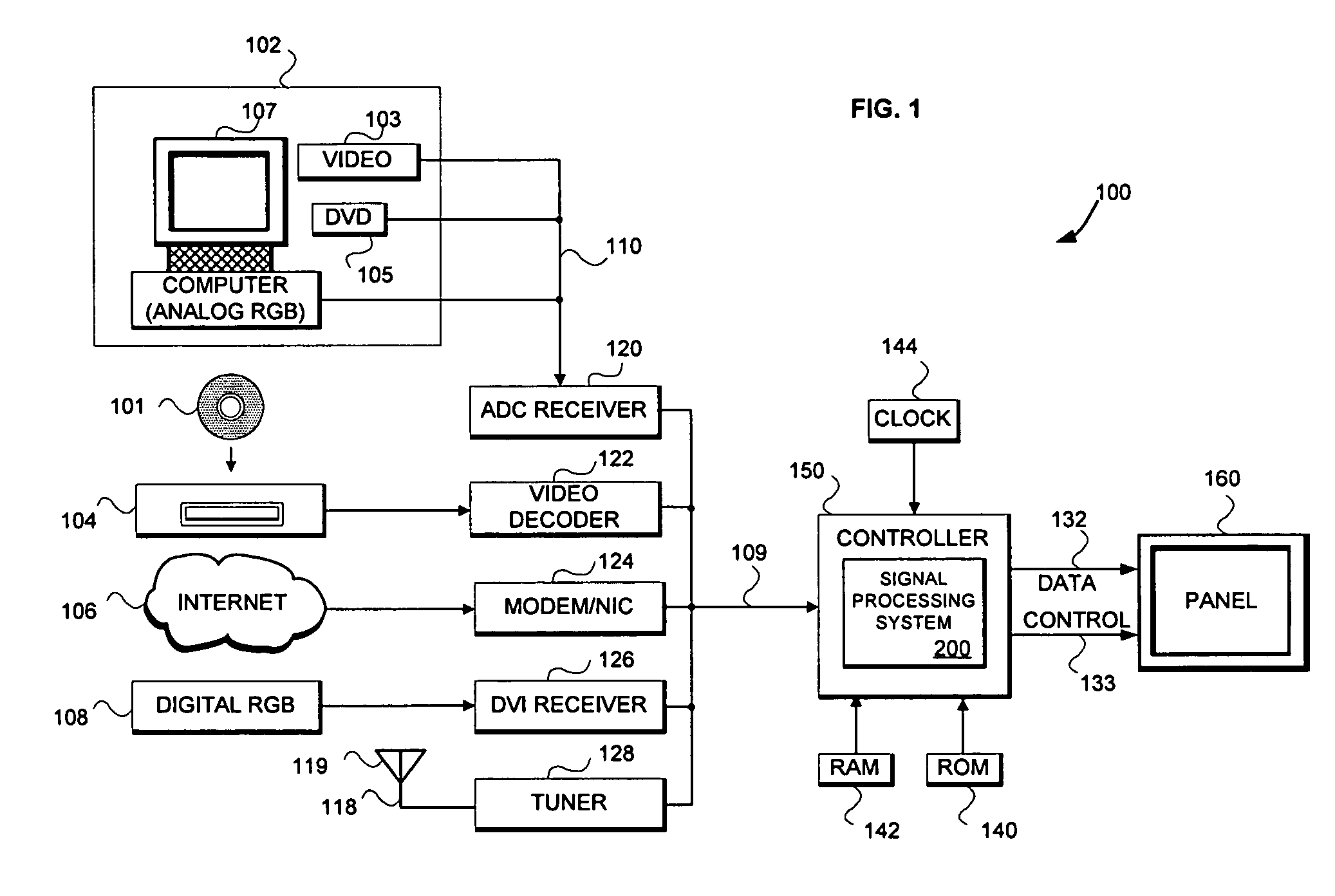
[0016]FIG. 1 is a block diagram of a system 100[n1]. Referring to FIG. 1, the system 100 includes a receiver 120 for receiving an analog image data signal 110, e.g., RGB or YPBPR signal, from a source 102. The source 102 may be a personal computer 107, a digital video disk player 105, set top box (STB) 103, or any other device capable of generating the analog or digital image data signal 110. The receiver 120 may be an analog-to-digital converter (ADC) or any other device capable of receiving an analog or digital video signal 109 from the analog image data 110. The receiver 120 converts the analog image data signal 110 into the digital image data 109 and provides it to a controller 150. A person of reasonable skill in the art knows well the design and operation of the source 102 and the receiver 120.

[0017]Likewise, a video receiver or decoder 122 may optionally decode an analog video signal 112 from a video source 104 when the input is in the composite or s-video format. The video s...


PUM


Abstract

I describe and claim a temporal comb filtering system and method. The temporal comb filter system includes a comb filter to temporally process separated luminance and chrominance components from an image field responsive to image data from at least one other image field and a panel to display the processed components. The comb filter includes a cross-chroma detector to detect luminance information within chrominance data from a first image field responsive to chrominance data from at least one other image field and a cross-luma detector to detect chrominance information within the luminance data from the first image field responsive to the luminance data from at least one other image field.

Description

REFERENCE TO RELATED APPLICATIONS[0001]This application claims priority from U.S. Provisional Application Ser. No. 60 / 642,087 filed Jan. 5, 2005. And this application is a continuation-in-part of prior application Ser. No. 10 / 833,979, filed Apr. 27, 2004 now U.S. Pat. No. 7,304,688, which claims priority from U.S. Provisional Application Ser. No. 60 / 472,280, filed May 20, 2003. We incorporate all of these applications here by reference.FIELD OF THE INVENTION[0002]This invention relates to image processing and, more specifically, to a system and method for temporally comb filtering a video signal.BACKGROUND OF THE INVENTION[0003]Composite video signals, commonly used in video broadcasts or transmissions, contain a brightness signal (luminance, luma or Y) and a color signal (chrominance, chroma or C), where the color signal is modulated into a color sub-carrier and added to the brightness signal prior to transmission. To effectuate demodulation of the color sub-carrier upon reception,...

Claims


Application Information

Patent Timeline
Patent Type & Authority Patents(United States)
IPC IPC(8): H04N9/77H04N9/78
CPCH04N9/78
Inventor WOODALL, NEIL D.
Owner PIXELWORKS SEMICON TECH SHANGHAI CO LTD
Why Eureka
Try Eureka