Network system, spanning tree configuration method and configuration program, and spanning tree configuration node

a network system and configuration method technology, applied in the field of spanning tree system, can solve the problems of increasing the size of the network, affecting the configuration of the spanning tree, and taking a long time to configure the spanning tree, so as to achieve the effect of increasing the number of nodes in the network, and increasing the topology

Inactive Publication Date: 2009-05-12
NEC CORP
View PDF14 Cites 8 Cited by
  • Summary
  • Abstract
  • Description
  • Claims
  • Application Information

AI Technical Summary

Benefits of technology

[0021]A first object of the invention is to provide a spanning tree system, a spanning tree configuration node, a spanning tree configuration method, and a spanning tree configuration program capable of shorting the configuration time of the spanning tree.
[0022]A second object of the invention is to provide a spanning tree system, a spanning tree configuration node, a spanning tree configuration method, and a spanning tree configuration program capable of restricting the failure affecting area at occurrence of a failure.

Problems solved by technology

The above conventional technique, however, has the following problems.
At first, in any convention technique, it takes a long time to configure the spanning tree.
Therefore, configuration of the spanning tree takes the longer time according to an increase in the size of the network.
Therefore, compared with the non-patent article 1, the technique of the non-patent article 2 can shorten the configuration time of the spanning tree, but complicate the shape of the topology and therefore, it takes the longer time to configure the spanning tree, according to an increase in the number of the nodes to be accommodated into a network.
At second, in any conventional technique, there is such a problem that at occurrence of a failure, it affects a large area.
In the conventional technique of the non-patent article 3, since the spanning tree configured by using the method of the non-patent article 2 is created in a multiphasic way, there is such a problem that at occurrence of a failure, it affects a large area, owing to the same reason as the non-patent article 2.

Method used


Image

  • Network system, spanning tree configuration method and configuration program, and spanning tree configuration node
  • Network system, spanning tree configuration method and configuration program, and spanning tree configuration node
  • Network system, spanning tree configuration method and configuration program, and spanning tree configuration node

Examples


first embodiment

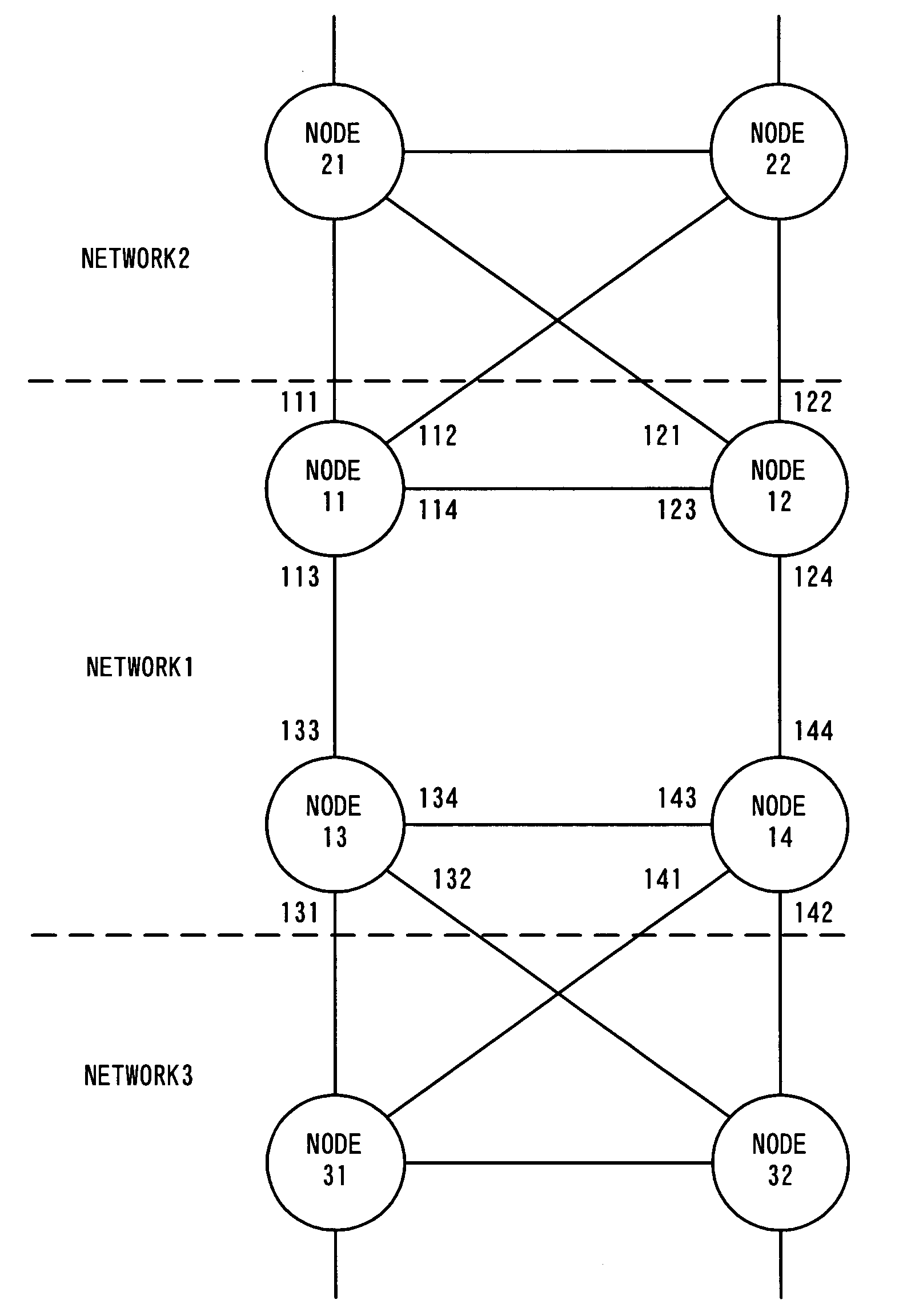
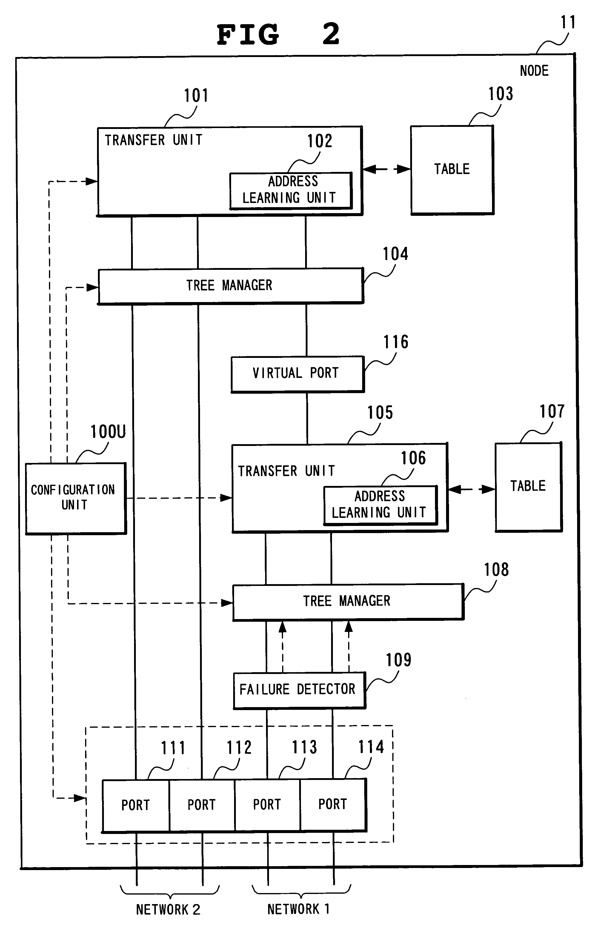
[0093]FIG. 2 is a block diagram showing the details of the structure of the node 11 in FIG. 1, according to a first embodiment.

[0094]In FIG. 2, a configuration unit 100U receives setting instructions as shown in the below (1) to (6), as the initial setting, by using a keyboard, a mouse, TELNET, WEB and the like. Based on the setting result of (1), each of the ports 111 to 114 is connected to the tree manager 104 for managing the spanning tree of the existing network or a failure detector 109; based on the setting results of (2) to (5), a transfer unit 101 and a transfer unit 105 are set; and based on the setting results of (5) and (6), the tree manager 104 and the tree manager 108 are also set.

[0095](1) whether each port belongs to the network 1 or the network 2,

[0096](2) the node ID of a destination node (a neighbor node connected to both the network 1 and the network 2) in the case of transmitting the BPDU frames for the spanning tree configuration for the network 2, to the networ...

operation example 3

OF THE FIRST EMBODIMENT

Single Failure Recovery In The Network 1

[0187]The third operation example in the first embodiment will be concretely described in detail with reference to FIG. 1, FIG. 2, FIG. 8, and FIG. 9.

[0188]In the operation example, the description will be made about the operation in the case of recovering a failure occurring in one of the four links forming the network 1, in the topology shown in FIG. 9. This operation example will be described assuming that a failure having occurred in the link between the node 11 and the node 12 is recovered.

[0189]In the network shown in FIG. 1, assume that the tree of the configuration as shown in FIG. 9 is formed according to the operation indicated by the operation example 2 and that the tree is stabilized.

[0190]In this state, when a link failure between the node 11 and the node 12 is recovered, keep alive frames will arrive at the failure detector 109 again within the specified time intervals. The failure detector 109 stops the fa...

operation example 4

OF THE FIRST EMBODIMENT

Configuration of the Spanning Tree by the Second Topology

[0197]The fourth operation example in the first embodiment will be concretely described in detail with reference to FIG. 10. The structure of the node of the invention in the fourth operation example is substantially the same as that in FIG. 2, but the number of the ports is different from that in FIG. 2.

[0198]The operation enabling the configuration of the spanning tree and the data transfer will be described in the topology shown in FIG. 10. In FIG. 10, the network 1 includes the nodes 11, 12, 13, and 14 of the invention, similarly to FIG. 1. The network 2 includes the nodes 21, 22, and 23, and the network 3 includes the nodes 31, 32, and 33. The nodes 21 to 23 and 31 to 33 do not have to be the node of the invention but may be the conventional spanning tree nodes.

[0199]In the node belong to the network 1, the tree manager 108 is used to configure the spanning tree of the network 1. At this point, the ...


PUM


Abstract

A node of a spanning tree system operating on a network connecting a plurality of nodes, comprises two transfer units which determines an output destination port, based on the destination MAC address of an input frame, two tree managers which configures a spanning tree according to a spanning tree protocol, and a virtual port of connecting the tree manager and the transfer unit.

Description

BACKGROUNDS OF THE INVENTION[0001]1. Field of the Invention[0002]The present invention relates to a spanning tree system, and more particularly to a spanning tree system, a spanning tree configuration node, a spanning tree configuration method, and its program capable of connecting the trees without causing a loop of path, in dividing a spanning tree into domains.[0003]2. Description of the Related Art[0004]Hitherto, this kind of spanning tree is used to prevent from data loops, by forming such a tree link as assuming that a loop does not exist logically even in the case where a loop ring physically exists in a network.[0005]As the conventional technique about the spanning tree, there exist the following examples.[0006]For example, in the standard documents (non-patent article 1) issued by the IEEE, titled as “IEEE•Standard•802.1D (IEEE Std 802.1D), 1998”, when a loop (ring) exists in a network, in order to prevent from data loops, a control method called a spanning tree is defined ...

Claims


Application Information

Patent Timeline
Patent Type & Authority Patents(United States)
IPC IPC(8): H04L12/28H04L12/44
CPCH04L12/462H04L45/48H04L45/00H04L45/76H04L12/28H04L12/46H04L12/44H04L9/40
Inventor ENOMOTO, NOBUYUKIUMAYABASHI, MASAKIHIDAKA, YOUICHIIWATA, ATSUSHI
Owner NEC CORP
Why Eureka
Try Eureka