
Lighting apparatus

a technology of light-emitting devices and light-emitting devices, which is applied in the direction of light-emitting devices, transportation and packaging, agriculture, etc., can solve the problems of large distances of light-emitting devices, damage to plants, and delicate balances to be struck, so as to minimize heat

Inactive Publication Date: 2009-05-19
INT GROWERS SUPPLY
View PDF5 Cites 95 Cited by
  • Summary
  • Abstract
  • Description
  • Claims
  • Application Information

AI Technical Summary

Benefits of technology

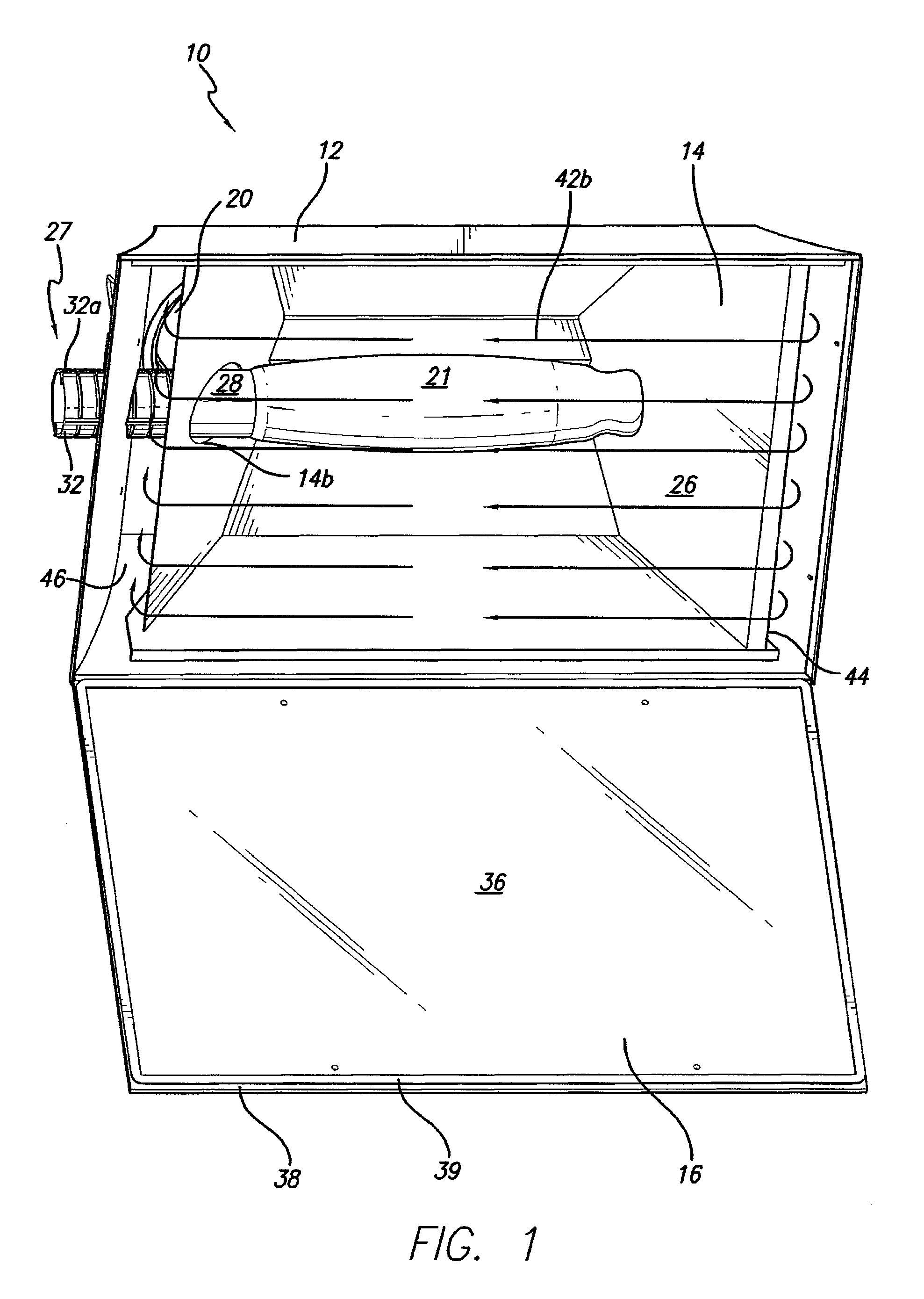
[0007]In accordance with another aspect of the present invention there is provided a method of minimizing heat emanating from a lighting apparatus. The method includes the steps of providing a lighting apparatus with an outer housing having an intake vent and an exhaust vent defined therein, an inner housing, a bulb and a cover, illuminating the bulb, thereby giving off heat, and moving air through the intake vent, through a first chamber defined between the inner and outer housings, across the inside surface of the cover, through a second chamber defined between the inner and outer housings and through the exhaust vent. In a preferred embodiment, the cross-sectional area of the first chamber decreases in an air flow direction and the cross-sectional area of the second chamber increases in an air flow direction.

Problems solved by technology

However, the bulbs not only emit light, they also emit heat, which can damage plants.
Therefore, a delicate balance has to be struck between how close the lighting devices are placed to the plant.
However, the more times the light hits a reflector before it gets to the plant, the larger the distance the light is traveling.
This results in a lower lumen output by the time it reaches the plant.
Prior art lighting reflectors radiate a lot of heat through the glass cover.

Method used


Image

  • Lighting apparatus
  • Lighting apparatus
  • Lighting apparatus

Examples


Embodiment Construction

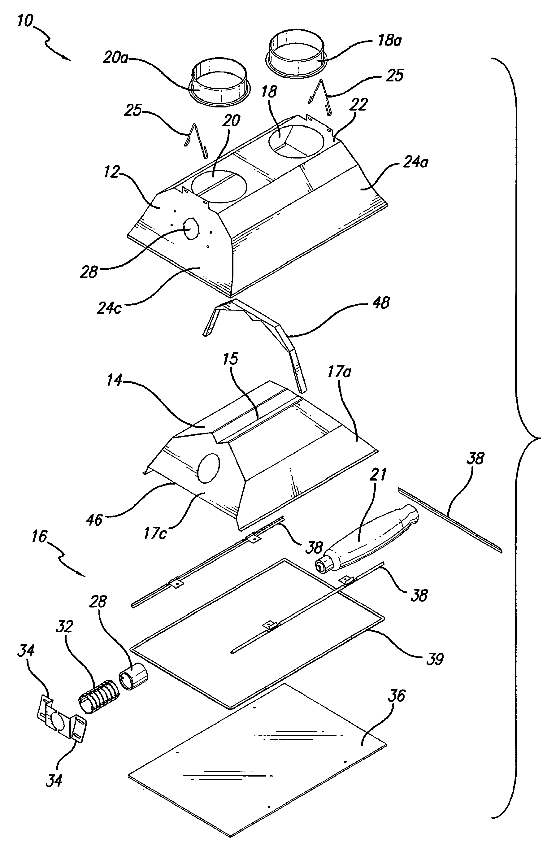
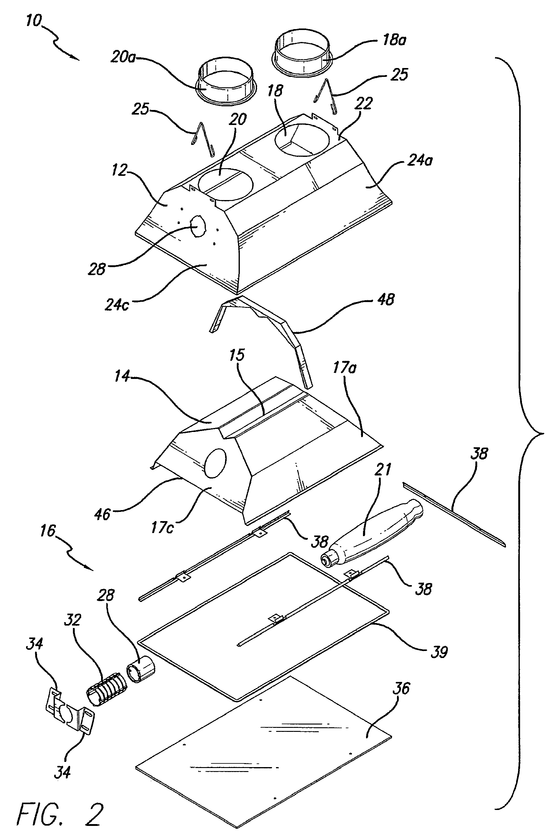
[0006]In accordance with a first aspect of the present invention, there is provided a lighting apparatus that includes an outer housing defining an intake vent and an exhaust vent, an inner housing disposed within the interior of the outer housing, and an air path defined between the outer housing and the inner housing. The outer housing includes a cover, a top and a plurality of side walls that define the interior, and the inner housing includes a top and a plurality of side walls that correspond to the top and plurality of side walls of the outer housing. The air entering the outer housing through the intake vent travels along the air path and exits the outer housing through the exhaust vent. In a preferred embodiment, a first air path segment is defined between a first side wall of the outer housing and a corresponding first side wall of the inner housing, a second air segment is defined adjacent to the inside surface of the cover, and a third air segment is defined between a sec...


PUM


Abstract

A lighting apparatus that includes an outer housing defining an intake vent and an exhaust vent, an inner housing disposed within the interior of the outer housing, and an air path defined between the outer housing and the inner housing. The outer housing includes a cover, a top and a plurality of side walls that define the interior, and the inner housing includes a top and a plurality of side walls that correspond to the top and plurality of side walls of the outer housing. The air entering the outer housing through the intake vent travels along the air path and exits the outer housing through the exhaust vent.

Description

[0001]This application claims the benefit of U.S. Provisional Application No. 60 / 891,490, filed Feb. 23, 2007, which is herein incorporated by reference in its entirety.FIELD OF THE INVENTION[0002]The present invention relates to a lighting apparatus, and more particularly to a light reflecting apparatus with an air cooling system.BACKGROUND OF THE INVENTION[0003]Lighting apparatuses in greenhouses are important. The higher the lumen output the better for the growing plant. Ideally, one wants to keep the light as close to the plant as possible. However, the bulbs not only emit light, they also emit heat, which can damage plants. Therefore, a delicate balance has to be struck between how close the lighting devices are placed to the plant.[0004]To maximize light output in a particular direction from a bulb that emits light in a 360 degree manner reflectors are used. However, the more times the light hits a reflector before it gets to the plant, the larger the distance the light is tra...

Claims


Application Information

Patent Timeline
Patent Type & Authority Patents(United States)
IPC IPC(8): F21V29/00
CPCA01G9/26F21V29/02A01G9/249F21V29/67Y02A40/25
Inventor TOWNSLEY, EVAN
Owner INT GROWERS SUPPLY
Learn More