Communication device locating system

a technology of communication device and locating system, which is applied in the direction of data switching network, eavesdropping prevention circuit, instruments, etc., can solve the problem of failure to determine the vicinity of the communication device, and achieve the effect of redundancy

Active Publication Date: 2009-05-19
AVAYA INC
View PDF109 Cites 50 Cited by
  • Summary
  • Abstract
  • Description
  • Claims
  • Application Information

AI Technical Summary

Benefits of technology

[0008]In accordance with further embodiments of the present invention, the communication device may itself include a passive identifier tag. Active identification devices that are provided as part of other communication devices, or that are specially provided, may provide information regarding passive identification tags in their vicinity (i.e. that can be read by the active device). Accordingly, by providing both active and passive identification capabilities in a communication device, redundancy can be achieved. In particular, failure of an active identification device associated with a communication device making a call, such as a request for emergency services, does not necessarily result in a failure to determine the vicinity of the communication device.
[0009]In accordance with further embodiments of the present invention, communication devices that are adjacent to a communication device initiating a request for emergency services or otherwise acting as a communication end point can be contacted by authorities receiving or aware of the request. Those authorities can request that a party associated with the other communication device verify the validity of the call and / or provide assistance until emergency service personnel arrive. Accordingly embodiments of the present invention can detect prank calls, and can provide verification of the nature and / or location of an emergency.

Problems solved by technology

In particular, failure of an active identification device associated with a communication device making a call, such as a request for emergency services, does not necessarily result in a failure to determine the vicinity of the communication device.

Method used


Image

  • Communication device locating system
  • Communication device locating system
  • Communication device locating system

Examples


Embodiment Construction

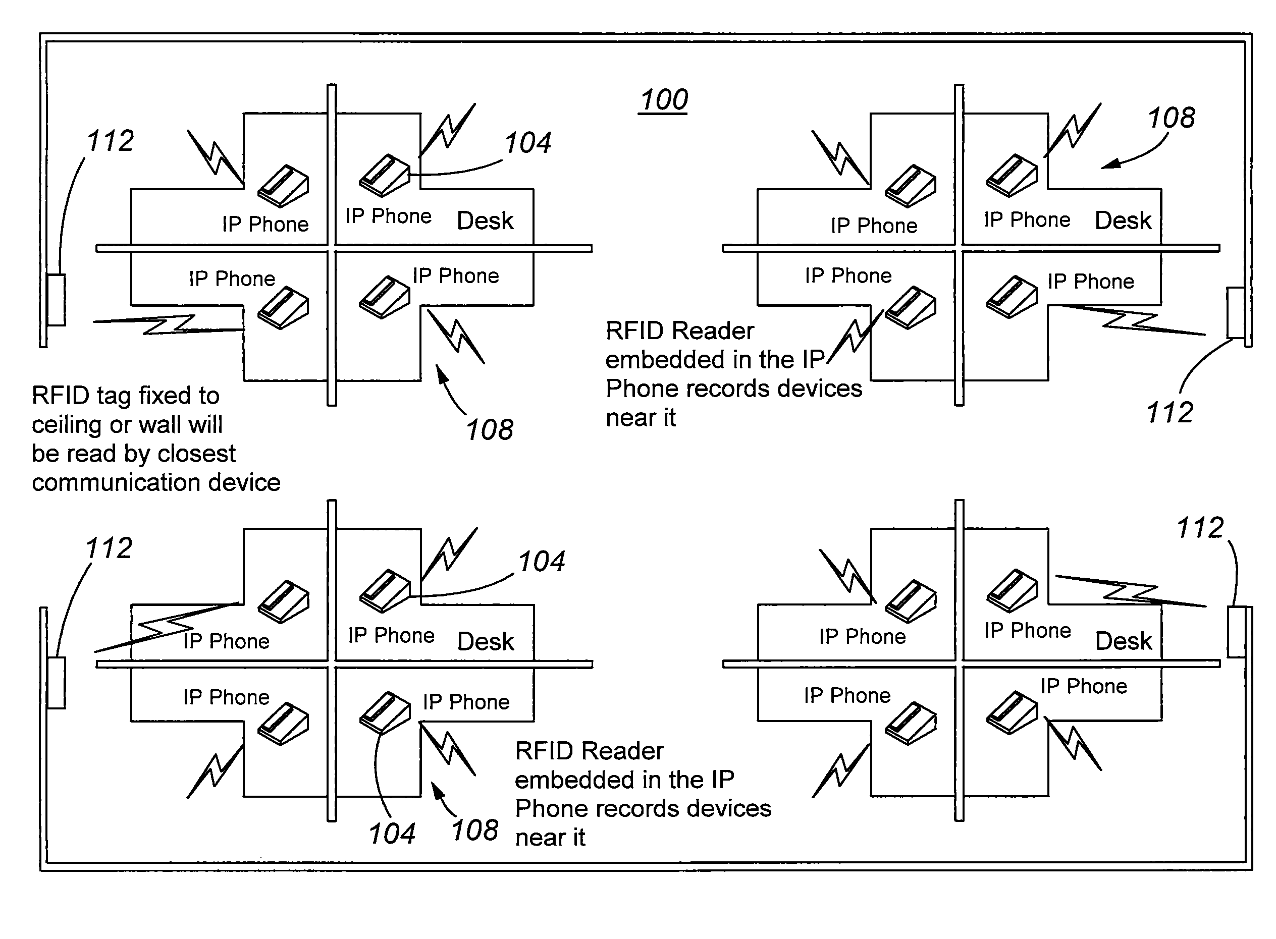
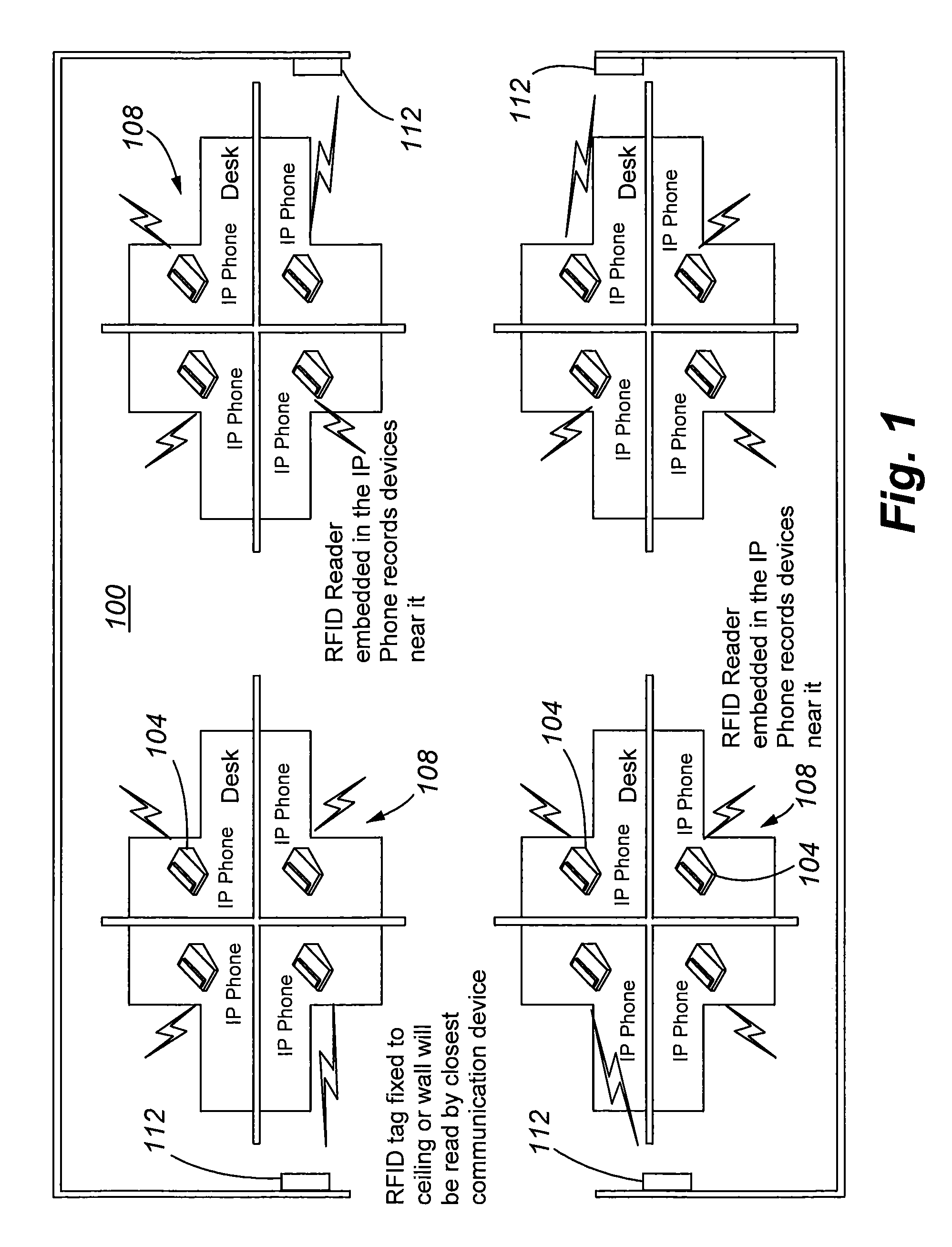
[0014]With reference to FIG. 1, a multiple line telephone system (MLTS) incorporating a communication device locating system 100 in accordance with embodiments of the present invention is illustrated. In general, the multiple line telephone system 100 includes a number of location identification enabled communication devices 104. The communication devices 104 may comprise Internet protocol telephones. As can be appreciated by one of skill in the art from the description provided herein, communication devices 104 may additionally or alternatively include cordless or wireless telephones. Other examples include Internet protocol soft phones, which may be implemented in connection with a general purpose computer. Still other examples of communication devices include personal digital assistants having communication capabilities.

[0015]As shown in FIG. 1, the communication devices 104 may be distributed about the interior of a building in offices or cubicles 108. The system 100 additionall...


PUM


Abstract

A system for determining the vicinity of a communication device within a communication network is provided. Individual communication devices are provided with an active identification reader capable of reporting information concerning identified passive identification tags to a location server. At least some passive identification tags have fixed or known locations, allowing a communication device capable of reading such a passive identification1 tag to be determined to be within a particular vicinity or area. Communication devices may also be provided with passive identification tags to allow other active identification readers to determine whether the communication device is in their vicinity.

Description

FIELD OF THE INVENTION[0001]The present invention is directed to providing location information related to a communication device. In particular, the present invention is related to determining the vicinity of a communication device by identifying other devices having a known location.BACKGROUND OF THE INVENTION[0002]Telecommunication regulations encourage that multi-line telephone systems (MLTS) report the exact location of a caller requesting emergency services to the public safety answering point (PSAP). Unlike traditional private branch exchange (PBX) solutions, multi-line telephone systems that make use of voice over Internet protocol (VoIP) solutions are unable to report the exact location of a caller.[0003]In order to provide location information in connection with VoIP telephone systems, a number of approaches have been suggested. For example, static records may be maintained regarding the location of each communication station. In order to provide automated retrieval of suc...

Claims


Application Information

Patent Timeline
Patent Type & Authority Patents(United States)
IPC IPC(8): H04W24/00
CPCG01S5/0289G01S13/75G01S13/76H04W4/02H04L67/18H04W84/18H04L67/52
Inventor FEGAN, CHRISTOPHER ALEXANDERMCNAMARA, PAUL THOMASMINHAZUDDIN, MUNEYB
Owner AVAYA INC
Why Eureka
Try Eureka