Sewing machine

a sewing machine and thread thread technology, applied in the field of sewing machines, can solve the problems of increasing the number of components, complicated configuration, and complicated thread thread threading through the thread holes of the respective loopers, and achieve the effect of convenient operation

Inactive Publication Date: 2009-05-26
JUKI CORP
View PDF11 Cites 13 Cited by
  • Summary
  • Abstract
  • Description
  • Claims
  • Application Information

AI Technical Summary

Benefits of technology

[0007]One or more exemplary embodiments of the present invention provide a sewing machine in which a threading work through loopers and a switching operation for switching use and nonuse of an upper looper can be easily carried out.

Problems solved by technology

While the needle thread is caught by the lower looper or while the lower looper thread is caught the upper looper, threading the threads through the thread holes of the respective loopers is complicated, because the thread caught by the looper needs to be pulled and the order of inserting the threads needs to be considered.
Thus, a configuration becomes is very complicated and the number of components increases.
In addition, operability is poor because a working space is restricted inside the sewing machine cover.

Method used


Image

  • Sewing machine
  • Sewing machine
  • Sewing machine

Examples


first exemplary embodiment

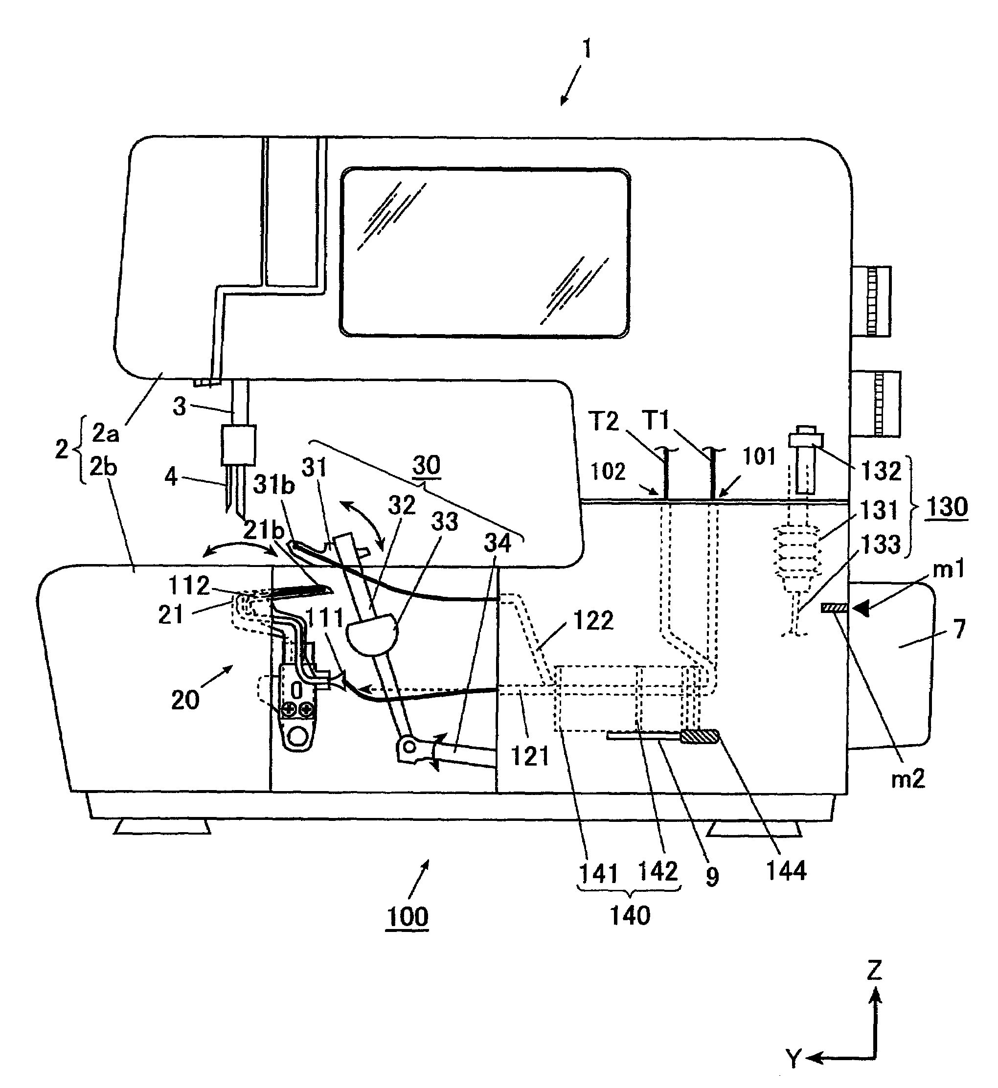
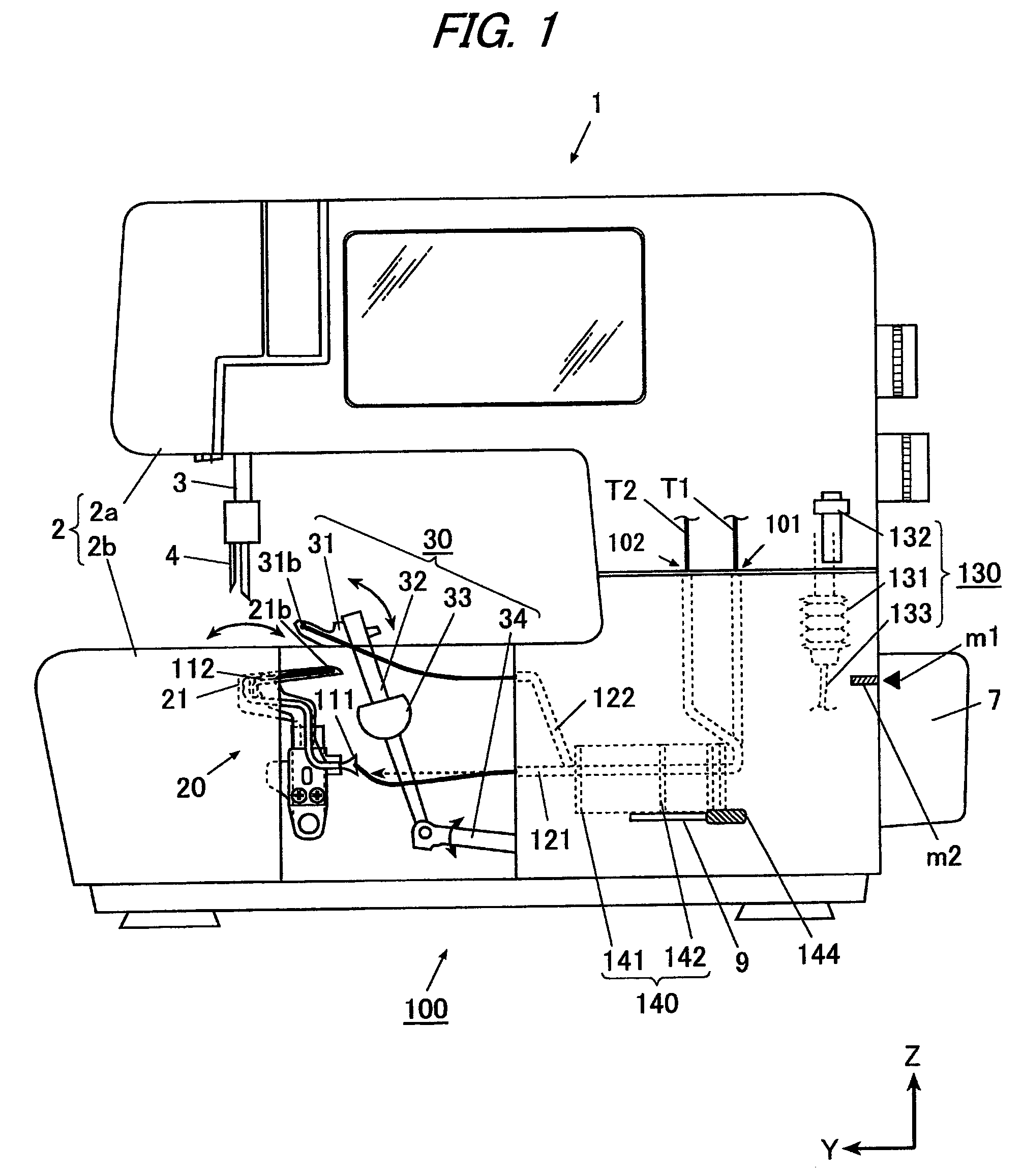
[0028]FIG. 1 is a front view of the sewing machine 1 according to a first exemplary embodiment of the invention.

[0029]As shown in FIG. 1, the sewing machine 1 includes a needle driving mechanism (not shown) which drives a needle 4 in the vertical direction by means of a sewing machine motor (not shown), a lower looper driving mechanism 20 and an upper looper driving mechanism 30 which cooperate with the needle 4 to form a seam, a threading device 100 for inserting a lower looper thread T1 and an upper looper thread T2 through thread holes 21b, 31b at tip portions of a lower looper 21 of the lower looper driving mechanism 20 and an upper looper 31 of the upper looper driving mechanism 30 respectively, and an upper looper use / nonuse switching mechanism 190 for switching a use and a nonuse of the upper looper 31. Each of the portions will be described below in detail.

[Needle Driving Mechanism]

[0030]The needle driving mechanism includes an upper shaft (not shown) rotated by the sewing m...

second exemplary embodiment

[0101]Next, a second exemplary embodiment of the invention will be described in detail with reference to FIGS. 6 to 16.

[0102]In the second exemplary embodiment, the same structures as those in the first exemplary embodiment have the same reference numerals, and repetitive explanation thereof will be omitted.

[0103]The second exemplary embodiment is different from the first exemplary embodiment in that there is provided a moving mechanism 240 supporting a thread guiding pipe 121 for inserting a lower looper thread T1 through a thread hole 21b of a lower looper 21 and a thread guiding pipe 122 for inserting an upper looper thread T2 through a thread hole 31b of an upper looper 31 at different heights. Further, according to the moving mechanism 240 of the second exemplary embodiment, a moving distance of the thread guiding pipe 122 is larger than that of the thread guiding pipe 121 (see FIG. 6). In the second exemplary embodiment, furthermore, driving links 283, 284 and a release link 2...


PUM


Abstract

A sewing machine includes an upper looper formed with a thread hole, an upper looper shaft which oscillates the upper looper between an upper position and a lower position, switching means operable to switch a coupled state and a decoupled state between the upper looper and the upper looper shaft, moving means for moving the upper looper, which has been decoupled from the upper looper shaft by the switching means, to the lower position, a thread guiding pipe formed with a thread discharging port, and first operating means operable to decouple the upper looper and the upper looper shaft via the switching means, and to move the thread discharging port of the thread guiding pipe to a position at which the thread discharging port is aligned with the thread hole of the upper looper in the lower position.

Description

CROSS-REFERENCE TO RELATED APPLICATION(S)[0001]The present application claims priority from Japanese Patent Application No. 2007-082280 filed on Mar. 27, 2007, the entire content of which is incorporated herein by reference.FIELD OF THE INVENTION[0002]The present invention relates to a sewing machine having a threading device for inserting threads through thread holes of upper and lower loopers, respectively.BACKGROUND ART[0003]Some sewing machines include a lower looper and an upper looper. The lower looper moves back and forth interlockingly with a vertical motion of a needle so as to be inserted into a loop of a needle thread formed below a throat plate. The upper looper is projectable above from the throat plate to insert an upper looper thread into a loop of a lower looper thread inserted in the loop of the needle thread by the lower looper. According to one technique, the sewing machine may be configured such that a use and a nonuse of the upper looper is selectable, so that a...

Claims


Application Information

Patent Timeline
Patent Type & Authority Patents(United States)
IPC IPC(8): D05B57/02D05B57/30
CPCD05B57/30
Inventor SADASUE, KAZUYA
Owner JUKI CORP
Why Eureka
Try Eureka