Cylinder head and internal combustion engine having the same

a technology of internal combustion engine and cylinder head, which is applied in the direction of machines/engines, cylinders, mechanical equipment, etc., can solve the problems of increasing cost, affecting unstable sliding orientation of valve lifters, so as to improve the dimensional accuracy of valve lifters, improve the dimensional accuracy, and reduce clearance

Active Publication Date: 2009-05-26
NISSAN MOTOR CO LTD
View PDF13 Cites 0 Cited by
  • Summary
  • Abstract
  • Description
  • Claims
  • Application Information

AI Technical Summary

Benefits of technology

[0007]In the conventional cylinder head described in the above-mentioned publication, a sliding length of the valve lifter within the valve lifter guide boss decreases in the cam rotational direction by the amount that the valve lifter guide boss is cut out. Therefore, the sliding orientation of the valve lifter may become unstable. Although the sliding orientation of the valve lifter may be stabilized by improving dimensional precision of the valve lifter and the valve lifter guide boss to reduce the clearance therebetween, improving the dimensional precision leads to an increase in cost.
[0008]Accordingly, one object of the present invention is to provide a cylinder head that can easily ensure the stability of the sliding orientation of the valve lifter while suppressing an increase in cost. Another object of the present invention is to provide an internal combustion engine that can reduce noise resulting from a rattling sound of the valve lifter.

Problems solved by technology

Therefore, the sliding orientation of the valve lifter may become unstable.
Although the sliding orientation of the valve lifter may be stabilized by improving dimensional precision of the valve lifter and the valve lifter guide boss to reduce the clearance therebetween, improving the dimensional precision leads to an increase in cost.

Method used


Image

  • Cylinder head and internal combustion engine having the same
  • Cylinder head and internal combustion engine having the same
  • Cylinder head and internal combustion engine having the same

Examples


second embodiment

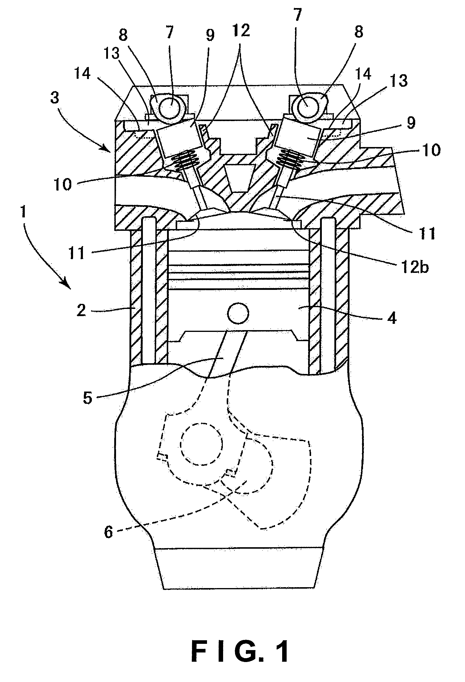
[0037]Referring now to FIGS. 7 and 8, an internal combustion engine in accordance with a second embodiment will now be explained. In view of the similarity between the first and second embodiments, the parts of the second embodiment that are identical to the parts of the first embodiment will be given the same reference numerals as the parts of the first embodiment. Moreover, the descriptions of the parts of the second embodiment that are identical to the parts of the first embodiment may be omitted for the sake of brevity. The parts of the second embodiment that differ from the parts of the first embodiment will be indicated with a single prime (′).

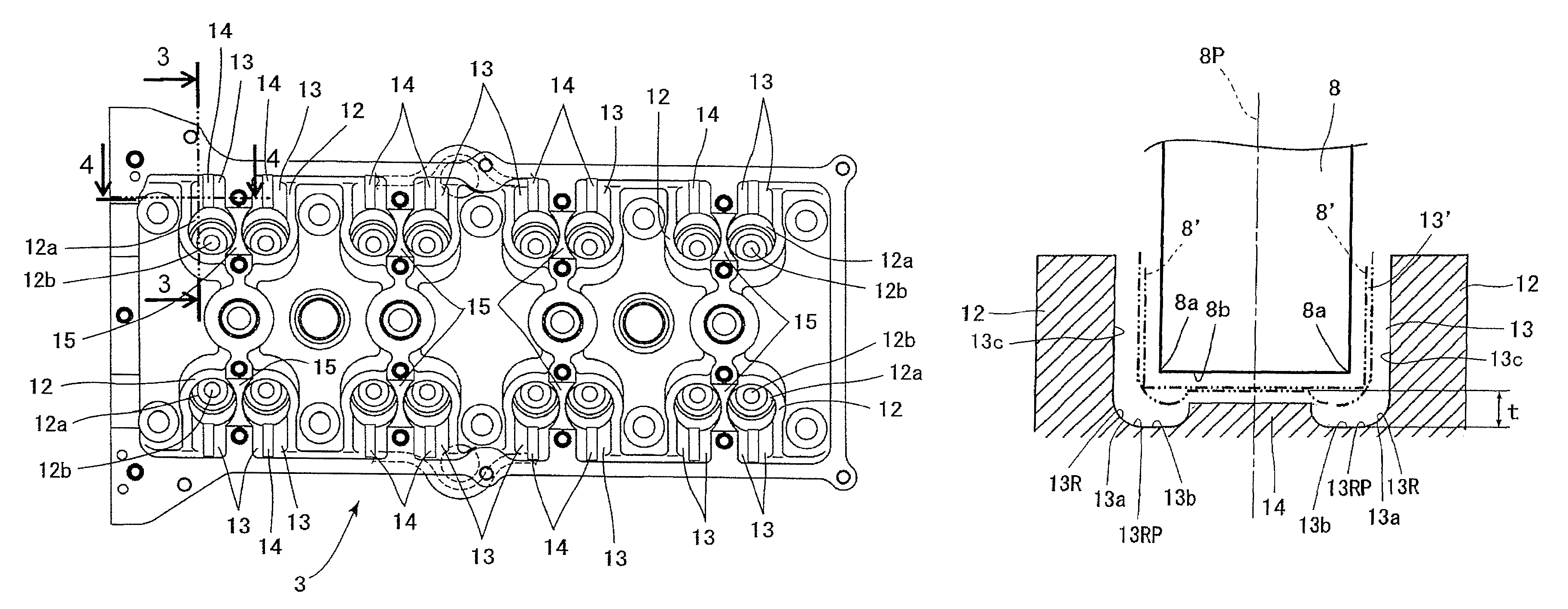
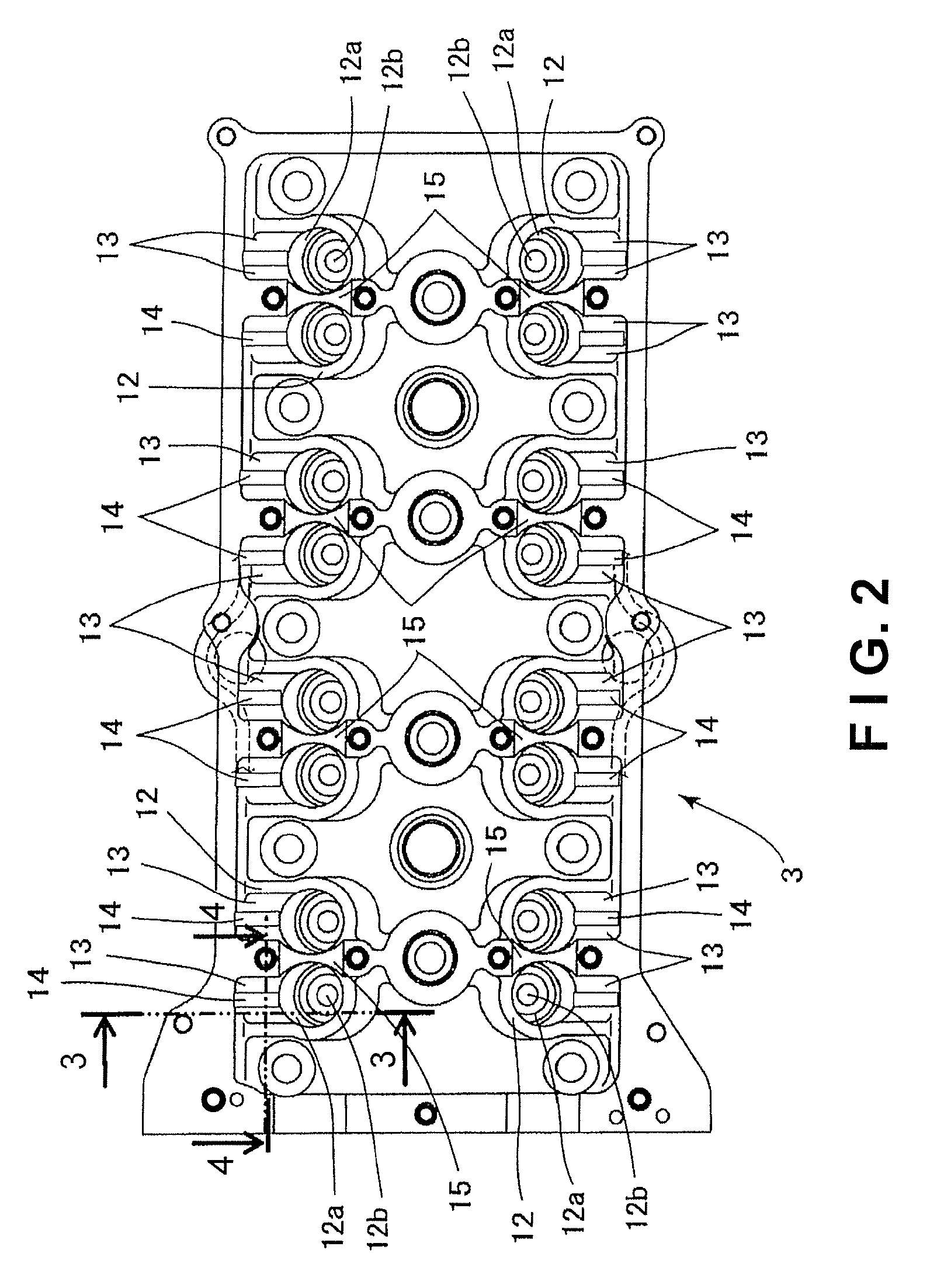
[0038]FIG. 7 is a top plan view of a cylinder head 3 of the engine 1 (shown in FIG. 1) in accordance with a second embodiment. FIG. 8 is an enlarged partial cross sectional view of the cylinder head 3 taken along a section line 8-8 of FIG. 7. The second embodiment is identical to the first embodiment except for a structure of a guide por...


PUM


Abstract

A cylinder head includes a lifter guide boss part, a concave relief groove portion and a guide portion. The lifter guide boss part defines a lifter bore arranged to slidably support a valve lifter. The concave relief groove portion has a predetermined width and a predetermined depth formed on the lifter guide boss part in a position corresponding to a rotation direction of a cam to avoid an interference between the cam and the lifter guide boss part. The relief groove portion includes a pair of groove side surfaces and a groove bottom surface with a pair of corner sections being formed between the groove bottom surface and the side groove surfaces. The guide portion protrudes from the groove bottom surface in a sliding direction of the valve lifter to slidably guide the valve lifter. The guide portion is spaced apart from the corner sections of the relief groove portion.

Description

CROSS-REFERENCE TO RELATED APPLICATIONS[0001]This application claims priority to Japanese Patent Application No. 2007-023031, filed on Feb. 1, 2007. The entire disclosure of Japanese Patent Application No. 2007-023031 is hereby incorporated herein by reference.BACKGROUND OF THE INVENTION[0002]1. Field of the Invention[0003]The present invention relates to a cylinder head and an internal combustion engine having the same.[0004]2. Background Information[0005]Japanese Patent No. 2523326 discloses a conventional cylinder head that includes a valve lifter guide boss forming a bore for supporting a valve lifter therein. In such a conventional cylinder head, a portion of the valve lifter guide boss corresponding to the rotational direction of a cam, which periodically pushes down the valve lifter, is cut out to prevent the cam and the valve lifter guide boss from interfering with each other.[0006]In view of the above, it will be apparent to those skilled in the art from this disclosure tha...

Claims


Application Information

Patent Timeline
Patent Type & Authority Patents(United States)
IPC IPC(8): F02F1/42
CPCF01L1/143
Inventor NISHIYAMA, KOJI
Owner NISSAN MOTOR CO LTD
Why Eureka
Try Eureka