Rigidity Reinforcement Ring and Tire Vulcanizing Method Using Same

a technology of rigidity reinforcement and tire vulcanization, which is applied in the direction of tyres, vehicle components, and separate inflatable inserts, etc., can solve the problems of not being able to meet the requirements of tire vulcanization, pneumatic tires may not exhibit the expected tire performance, and applicable tire shapes, etc., to achieve the effect of increasing the degree of freedom in tire design, reducing the thickness of the shoulder portion of the tire, and increasing the dimensional precision of the pneumati

Inactive Publication Date: 2017-10-12
YOKOHAMA RUBBER CO LTD
View PDF12 Cites 0 Cited by
  • Summary
  • Abstract
  • Description
  • Claims
  • Application Information

AI Technical Summary

Benefits of technology

[0031]According to the rigidity reinforcement ring and the tire vulcanizing method that uses the rigidity reinforcement ring of the present technology, vulcanization molding is performed with the rigidity reinforcement ring disposed between the inner circumferential surface of the green tire corresponding to the tread portion and the outer peripheral surface of the bladder corresponding to the tread portion, the rigidity reinforcement ring having a tensile stress greater than a compressive stress in the circumferential direction. As a result, an outer diameter of the bladder is kept from ballooning, thereby making it possible to limit a shape of the inner circumferential surface of the tire and regulate a thickness of the tire in the tire radial direction. Further, the bladder is kept from expanding in the tire radial direction and expansion in the tire width direction is increased, making it possible to decrease a thickness in a shoulder portion of the tire. This makes it possible to increase the dimensional precision of the pneumatic tire. Furthermore, the outer diameter and width of the rigidity reinforcement ring can be adjusted as appropriate, making it possible to further increase the degree of freedom in tire designing. Moreover, the rigidity reinforcement ring may be simply used with an existing bladder, thereby maintaining productivity and not causing an increase in manufacturing costs. Further, in this tire vulcanizing method, the green tire is vulcanized using a rigidity reinforcement ring of (1) to (13) described above, thereby increasing dimensional precision and making it possible to manufacture a high quality pneumatic tire in a stable manner at low cost.
[0032]According to the rigidity reinforcement ring and the tire vulcanizing method using the rigidity reinforcement ring of the second aspect of the present technology, bladder-less vulcanization is performed with the rigidity reinforcement ring disposed so as to come into contact with the entire inner side surface of the region corresponding to that from the tread portion to the bead portion of the green tire, the rigidity reinforcement ring having a tensile stress greater than a compressive stress in the circumferential direction. As a result, this rigidity reinforcement ring makes an inner surface shape of the tire excellent and increases dimensional precision. Further, the rigidity reinforcement ring may be simply disposed on the inner circumferential surface of the green tire, making it possible to maintain favorable bladder-less vulcanization productivity. Further, in this tire vulcanizing method, the green tire is vulcanized without a bladder using a rigidity reinforcement ring of (18) to (20) described above, thereby increasing dimensional precision and making it possible to manufacture a high quality pneumatic tire in a stable manner at low cost.

Problems solved by technology

However, in vulcanization molding that uses a vulcanization bladder, the constituent members of the pneumatic tire may move, causing the members to not be disposed as designed.
In such a case, the pneumatic tire may not exhibit the expected tire performance.
However, in the vulcanizing method that uses the rigid inner ring, difficulties arise in coping with thermal expansion of the tire during vulcanization, causing problems such as a limit to applicable tire shapes, difficulties in removing the vulcanized tire from the inner mold, which results in low productivity, and increased manufacturing costs.
However, in bladder-less vulcanization, the heating medium may not be adequately pressed into the mold in regions where the green tire is thick, resulting in problems such as a limit to the applicable tire shapes, and inadequacies in an inner surface shape and the dimensional precision of the vulcanized tire.

Method used


Image

  • Rigidity Reinforcement Ring and Tire Vulcanizing Method Using Same
  • Rigidity Reinforcement Ring and Tire Vulcanizing Method Using Same
  • Rigidity Reinforcement Ring and Tire Vulcanizing Method Using Same

Examples


working examples 1 to 4

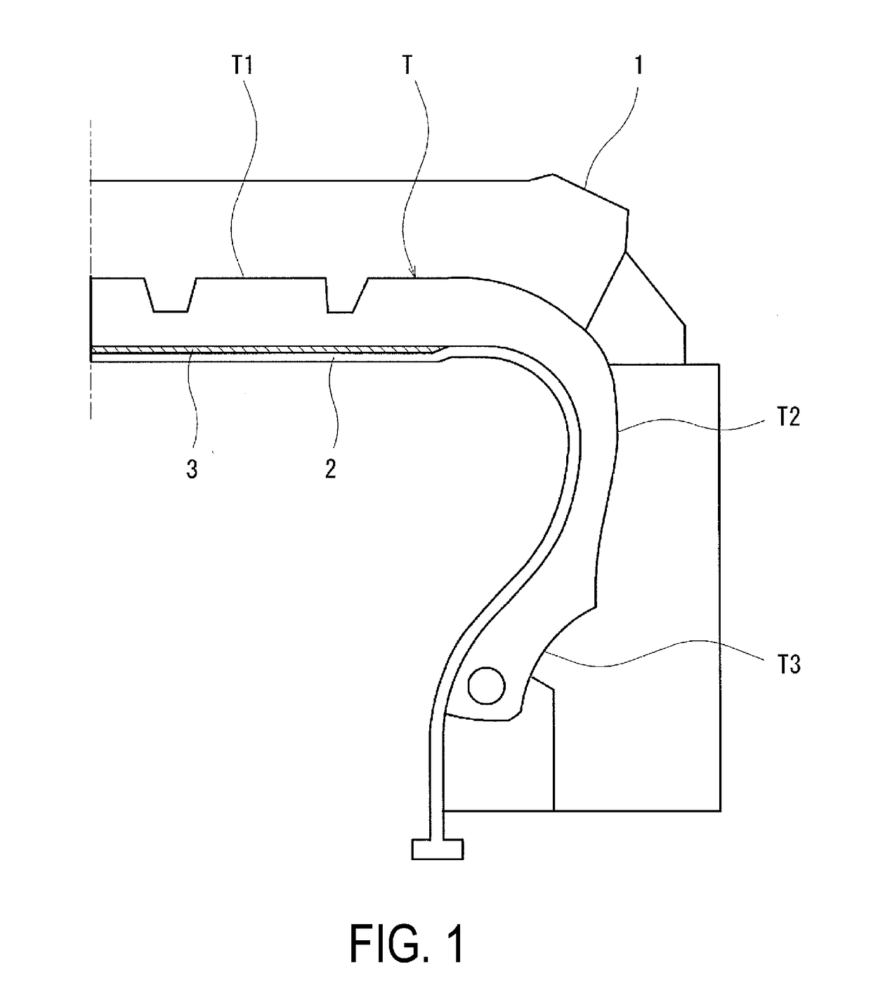
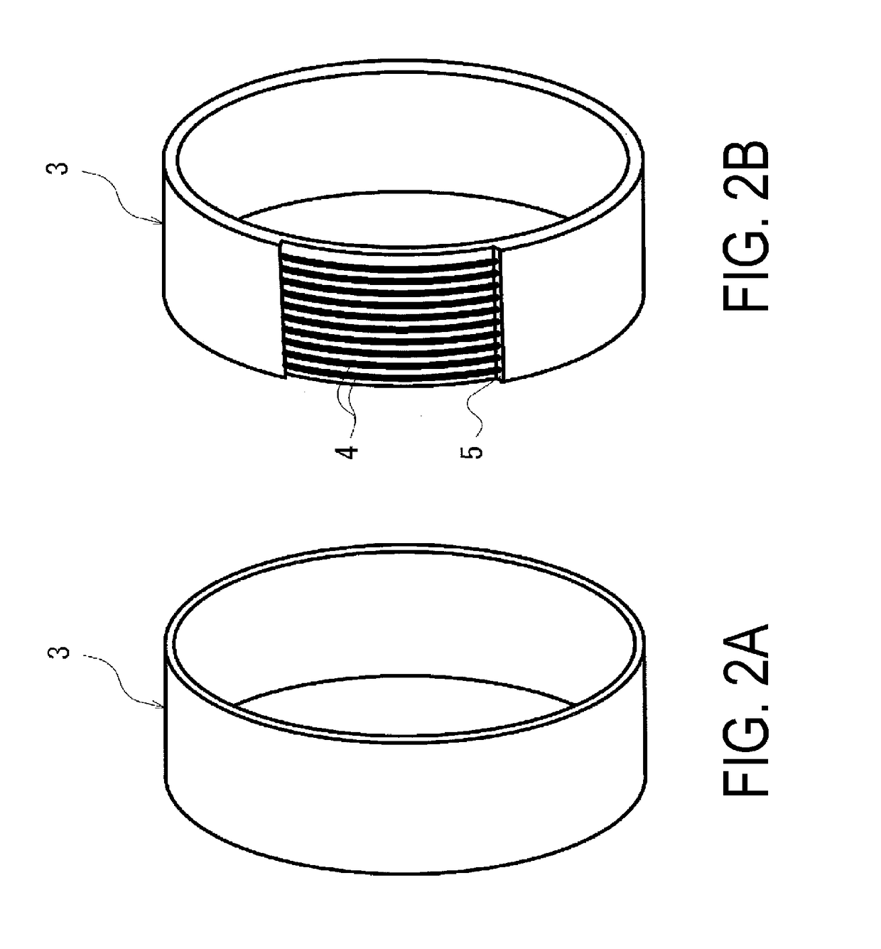
[0104]Green tires (tire size 205 / 55R16) having identical specifications were manufactured. Each of the green tires was formed by performing vulcanization molding with a rigidity reinforcement ring in Working Examples 1 to 4, and without a rigidity reinforcement ring in Comparative Example 1. Note that the rigidity reinforcement ring used was a cylindrical ring (diameter: 570 mm, thickness t: 2.3 mm) obtained by winding a polyester fiber cord (a cord having a total linear density of 2200 dtex and a twisted structure of 46×46 (two-cord twist)) in a spiral-like manner in the tire circumferential direction using an end count of 50 per 50 mm, covering the wound body with a butyl rubber, and performing vulcanization. Further, a rigidity reinforcement ring without a tapered portion was used in Working Example 1, and a rigidity reinforcement ring with tapered portions having the dimensions shown in Table 1 was used in each of the Working Examples 2 to 4. The rigidity reinforcement rings use...

working examples 5 and 6

[0111]Pneumatic tires (tire size 205 / 55R16) having identical specifications were manufactured. The pneumatic tires of Working Examples 5 and 6 and Comparative Examples 2 and 3 were manufactured by performing vulcanization molding by bladder surface processing or by using a rigid inner ring in Comparative Examples 2 and 3, and by performing vulcanization molding using a rigidity reinforcement ring in Working Examples 5 and 6.

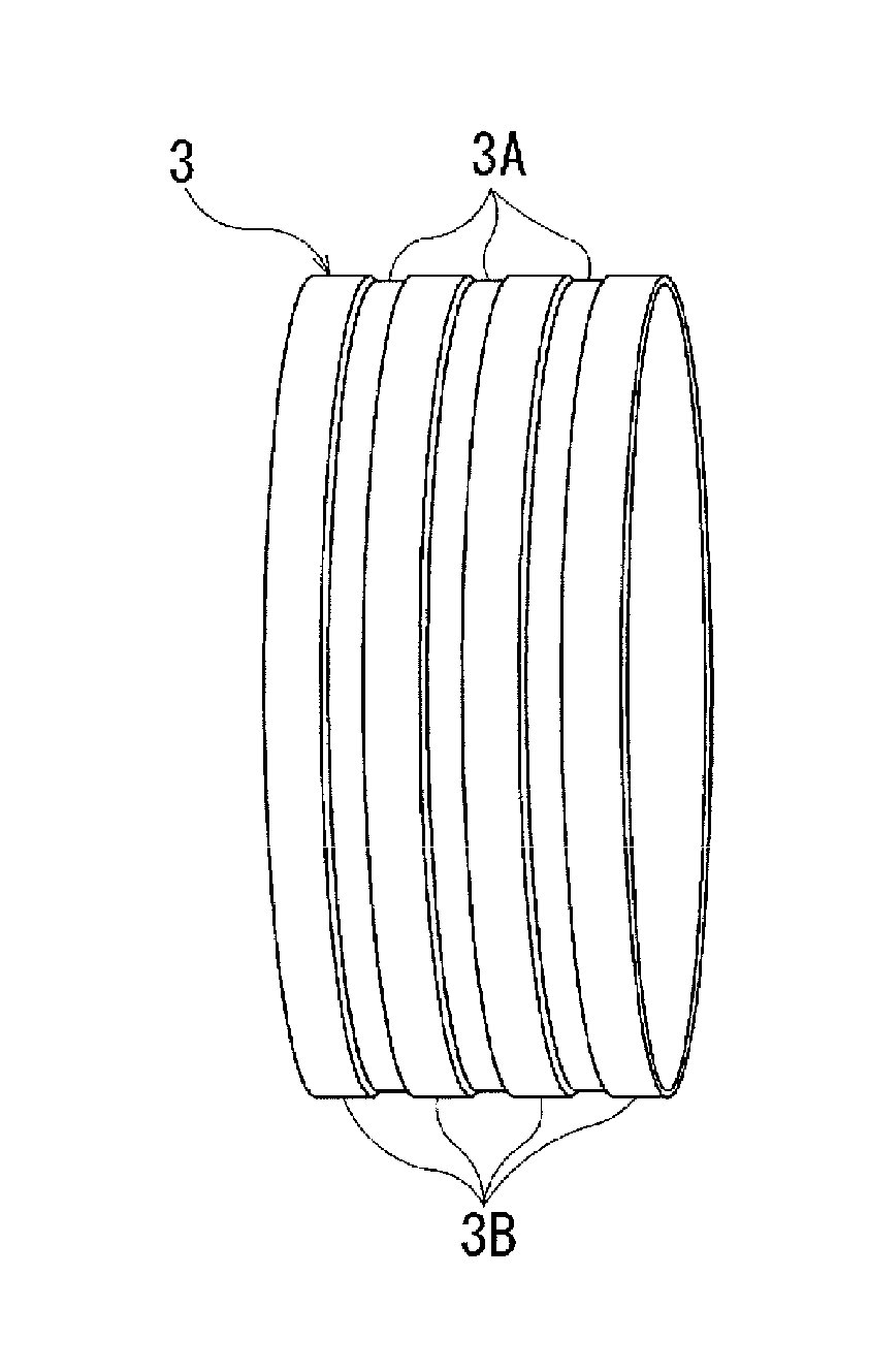
[0112]Note that, in the rigidity reinforcement ring of Working Example 5, an inclined surface was not provided to either end portion of the rigidity reinforcement ring, as illustrated in FIG. 5. In the rigidity reinforcement ring of Working Example 6, an inclined surface was provided to each surface that comes into contact with the vulcanization bladder at a stepped portion formed by thick portions and thin portions having varied thicknesses in accordance with the depths of the recesses of the rigidity reinforcement ring, as illustrated in FIG. 6. Further, an inc...

working example 7

[0119]Green tires (tire size 205 / 55R16) having identical specifications were manufactured. Bladder-less vulcanization was performed using the rigidity reinforcement ring illustrated in FIG. 13 in Working Example 7, and without a rigidity reinforcement ring in Comparative Example 4. Note that the rigidity reinforcement ring used was a ring designed to come into contact with the entire inner side surface of the region corresponding to that from the tread portion to the bead portion. Further, the ring used was a cylindrical ring (diameter: 570 mm, thickness t: 2.3 mm) obtained by winding a polyester fiber cord (a cord having a total linear density of 2200 dtex and a twisted structure of 46×46 (two-cord twist)) in a spiral-like manner in the tire circumferential direction using an end count of 50 per 50 mm, covering the wound body with a natural rubber, and performing vulcanization.

[0120]The inner surface shapes of the pneumatic tires obtained by bladder-less vulcanization in Working Ex...


PUM

PropertyMeasurementUnit
thicknessaaaaaaaaaa
thicknessaaaaaaaaaa
thicknessaaaaaaaaaa

Abstract

Provided is a pneumatic tire vulcanizing method which includes the steps of setting a green tire in a mold, inserting a bladder inside the green tire, and expanding the bladder to press the bladder to an outer side in the tire radial direction and perform vulcanization molding. The bladder is expanded with a rigidity reinforcement ring interposed between an inner circumferential surface of a region of the green tire corresponding to a tread portion and an outer circumferential surface of a region of the bladder corresponding to the tread portion.

Description

TECHNICAL FIELD[0001]The present technology relates to an annular member used in vulcanization molding of a pneumatic tire, and a tire vulcanizing method using the same.BACKGROUND ART[0002]Often, as a method of vulcanization molding a pneumatic tire, a green tire is set in a mold, a vulcanization bladder is inserted in the green tire, and steam or the like is injected into the vulcanization bladder, filling and expanding the vulcanization bladder and causing the green tire to become pressurized and heated. However, in vulcanization molding that uses a vulcanization bladder, the constituent members of the pneumatic tire may move, causing the members to not be disposed as designed. In such a case, the pneumatic tire may not exhibit the expected tire performance. Further, in order to manufacture a pneumatic tire having high performance, a disposition accuracy of the tire components needs to be further increased.[0003]To increase a dimensional precision of the pneumatic tire and thus in...

Claims


Application Information

Patent Timeline
Patent Type & Authority Applications(United States)
IPC IPC(8): B60C5/08B60C99/00
CPCB60C99/00B60C5/08B29D30/0654B29D30/0662B29D2030/0659
Inventor SATOH, HAJIMEYAMAMURA, KENTA
Owner YOKOHAMA RUBBER CO LTD
Why Eureka
Try Eureka