Self-adjusting bicycle brake assembly

a bicycle and self-adjusting technology, applied in the direction of cycle brakes, braking elements, cycle equipment, etc., can solve the problems of increasing friction and additional work, dragging against the bicycle rim, and many existing bicycles without effective anti-lock capability, etc., to achieve the effect of minimizing brake damage, facilitating adjusting to other bicycle brakes, and facilitating modification of the stopping parameters of the brake assembly

Inactive Publication Date: 2009-05-26
KATO GILBERT F
View PDF13 Cites 20 Cited by
  • Summary
  • Abstract
  • Description
  • Claims
  • Application Information

AI Technical Summary

Benefits of technology

[0025]The current brake assembly also compensates for irregularities and tire rim defects and road irregularities, thereby minimizing brake damage. In particular the torsion spring coil flexes whenever the wheel strikes potholes and bumps. The two spring arms can flex individually in different directions simultaneously, thereby providing a constant force between the brake pads and wheel rim.
[0026]The current br

Problems solved by technology

Many existing bicycles lack effective anti-lock capability.
Furthermore, most brake systems do not self-align, thereby causing one brake shoe with increased applied force from the bicycle cable, to drag again

Method used


Image

  • Self-adjusting bicycle brake assembly
  • Self-adjusting bicycle brake assembly
  • Self-adjusting bicycle brake assembly

Examples


Embodiment Construction

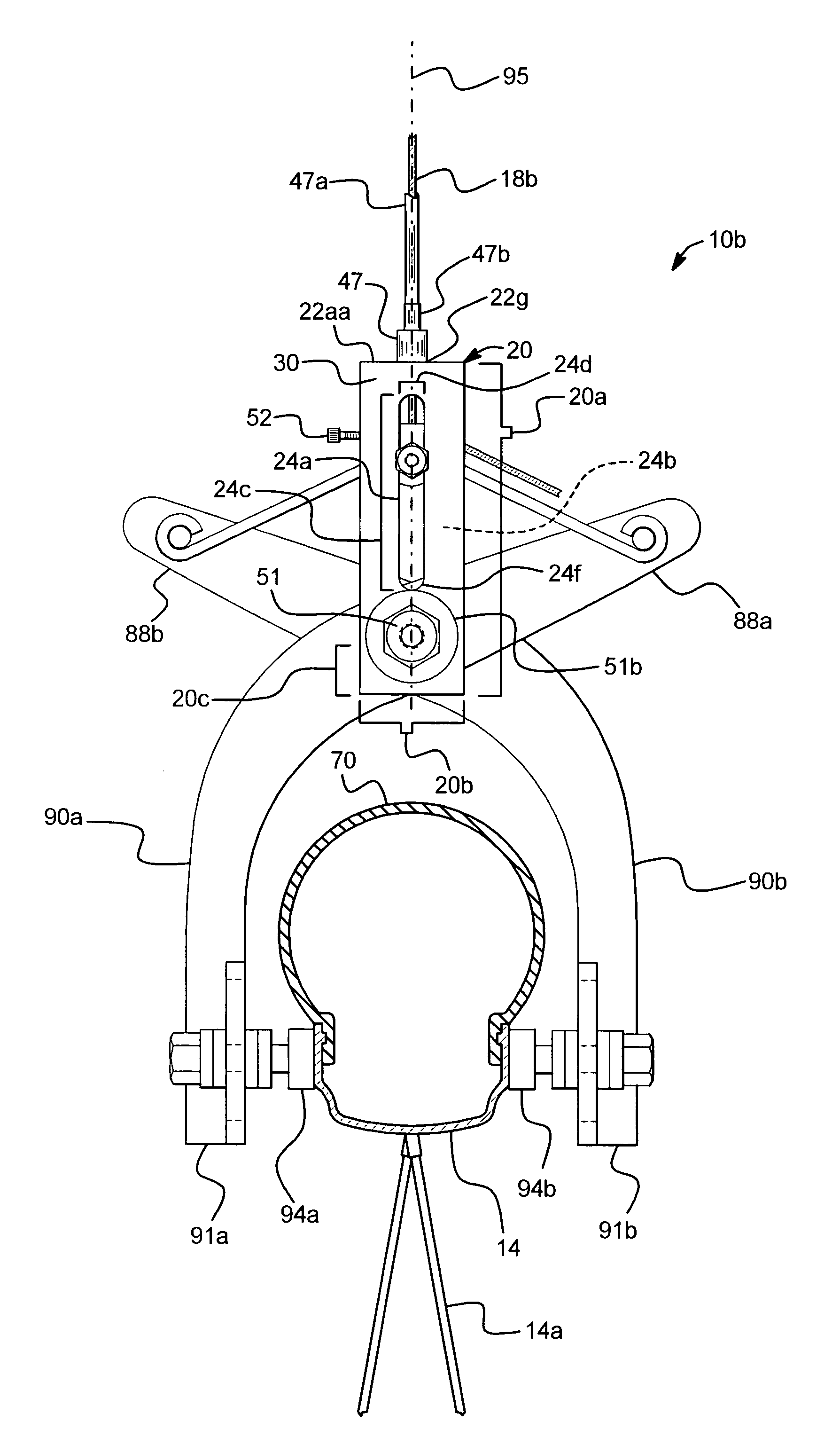
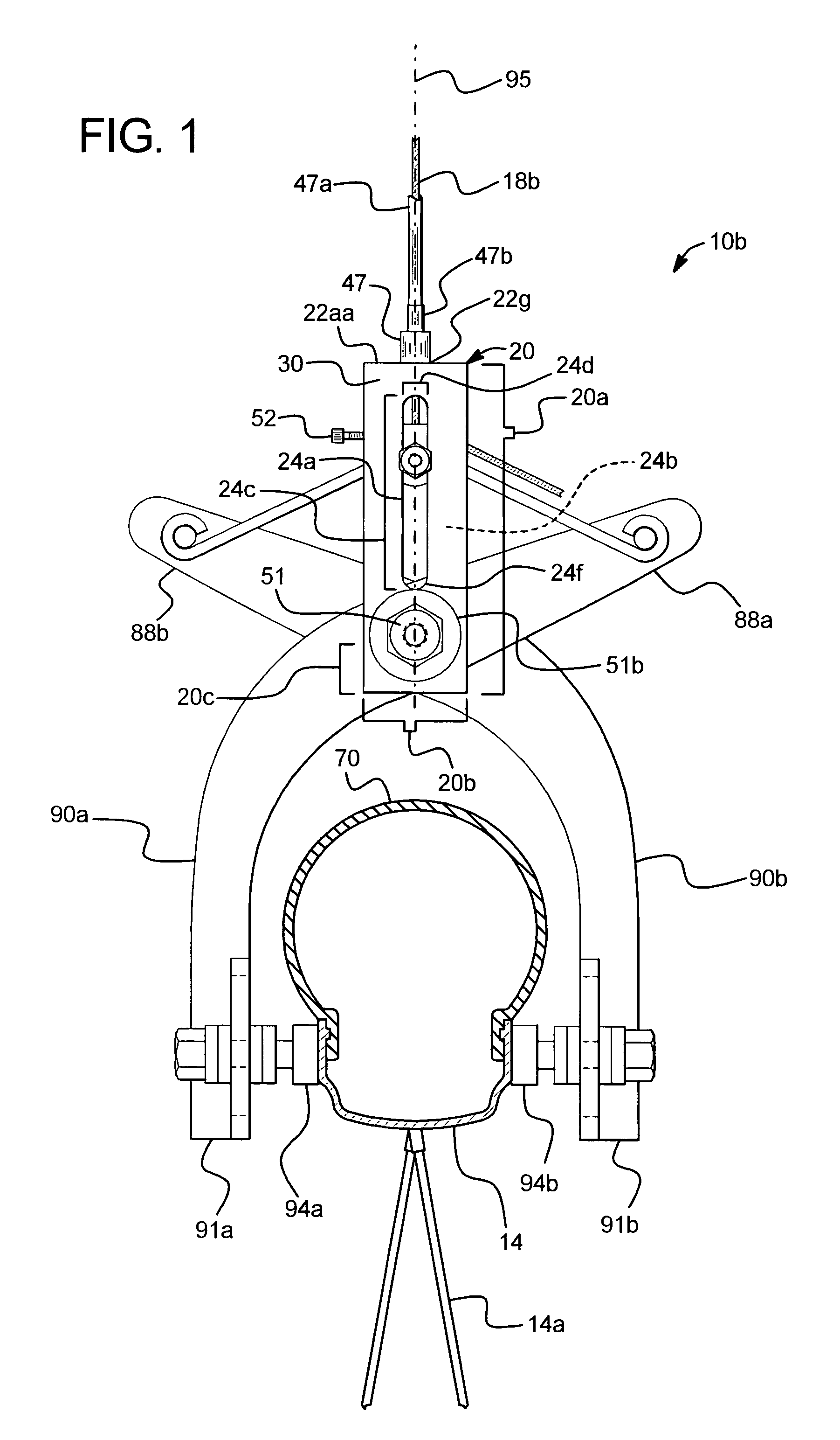
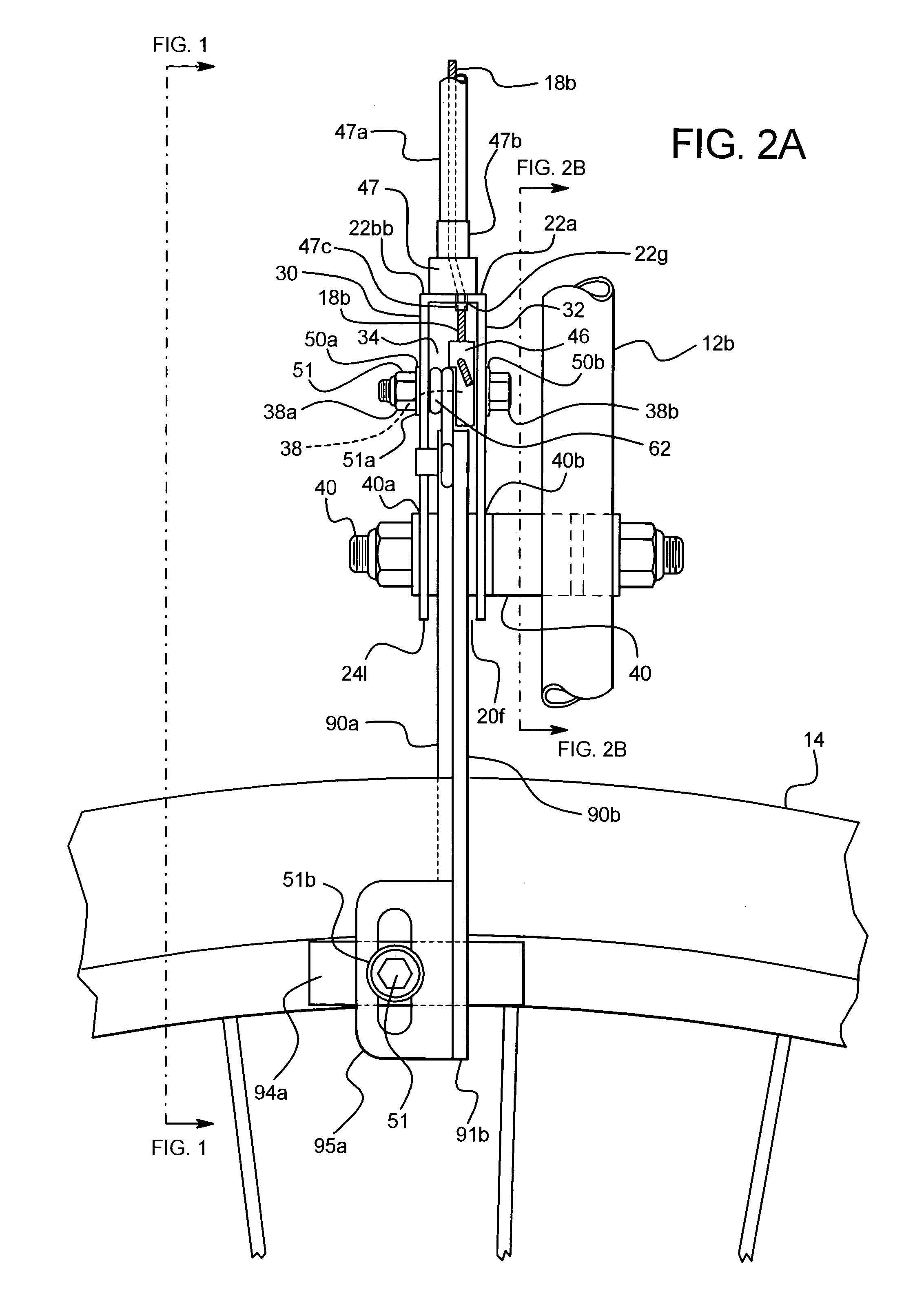
[0042]Brake arms of a bicycle brake assembly can be cantilevers or calipers. Brake arms can also comprise other varieties of pivoting or flexing bilateral devices which contain perpendicularly aligned components, often referred to as “brake shoes.” Upon receiving force from other brake components, brake shoes move towards the bicycle rim and press upon it, thereby halting movement of the bicycle wheel.

Brake Assembly 10 in the Preferred Embodiment

[0043]In the preferred embodiment, brake arms comprise calipers 90a, 90b, infra. Referring initially to FIG. 3, anterior bicycle brake assembly 10a [‘anterior assembly 10a’] is located anterior to anterior bicycle fork 12a. Anterior assembly 10a attaches to anterior bicycle fork 12a by anterior bracket 13a (not seen). Anterior assembly 10a attaches to anterior handlebar lever 95a by anterior bicycle cable 18a.

[0044]Still referring to FIG. 3, posterior bicycle brake assembly 10b [‘posterior assembly 10b’] is located posterior to bicycle seat...


PUM


Abstract

Described herein is a bicycle brake assembly which comprises a torsion spring attached to brake arms by bosses. The torsion spring simultaneously attaches to a slide bolt, while the slide bolt attaches to a slide member. When the rider applies pressure upon the bike handlebar levers, the tension from the bicycle cable pulls the slide bolt and engaged slide member upward. The torsion spring attached to the slide bolt flexes, thereby pulling the upper brake arms toward each other. The lower brake arm movement towards the bicycle rim results in abutment of brake shoes against the bicycle rim.

Description

RELATED APPLICATIONS[0001]This application is related to U.S. Provisional Application No. 60 / 718,461 filed on Sep. 19, 2005.BACKGROUND OF THE INVENTION[0002]The present invention relates to bicycle brakes comprising bicycle cables and handlebar levers. In particular, this present invention relates to a new bicycle brake assembly which includes a torsion spring and slide guide with slide member. The current bicycle brake assembly exhibits: self-alignment, uniform forces upon both brake shoes, simplicity of construction and simultaneous engagement of brake shoes.[0003]Many existing bicycles lack effective anti-lock capability. For example, the rider initially depresses prior art brake levers suddenly with maximum effort. The maximum braking force for the rotating wheels occurs just prior to zero rotation, and then the wheels stop rotating and skid.[0004]Furthermore, most brake systems do not self-align, thereby causing one brake shoe with increased applied force from the bicycle cable...

Claims


Application Information

Patent Timeline
IPC IPC(8): B62L1/06
CPCB62L1/10
Inventor KATO, GILBERT F.
Owner KATO GILBERT F
Why Eureka
Try Eureka