Hand-held drive-in power tool

a technology of drive-in power tools and power tools, which is applied in the direction of manufacturing tools, stapling tools, nailing tools, etc., can solve the problems of mechanical springs, loss of substantial portion of energy stored in springs, and much greater losses, so as to reduce the expansion speed of drive springs and reduce the loss of kinetic energy. , the effect of increasing the speed

Active Publication Date: 2009-05-26
HILTI AG
View PDF18 Cites 25 Cited by
  • Summary
  • Abstract
  • Description
  • Claims
  • Application Information

AI Technical Summary

Benefits of technology

[0011]These and other objects of the present invention, which will become apparent hereinafter, are achieved by arranging a transmission mechanism between the drive spring and the drive-in ram. This transmission mechanism provides for a lower expansion speed of the drive spring which, in turn, results in a smaller kinetic energy losses in the spring, on one hand and, on the other hand, provides for an increased speed and a longer acceleration path. As a result, a high drive-in speed and, simultaneously, a high setting or drive-in energy are obtained.
[0013]A good design of the drive-in power tool with the optimal use of the drive spring can be achieved when the transmission mechanism has a transmission ratio of at least 1:1.5.
[0014]Advantageously, the transmission mechanism has a transmission ratio between 1:2 and 1:4. Thereby, an optimal compromise between the additional weight of the transmission mechanism and speed gain of the drive-in ram is achieved.

Problems solved by technology

However, mechanical springs have a drawback in comparison with gas spring that consists in that upon a rapid expansion, a substantial portion of the energy, which is stored in the spring becomes lost as it has to be used for accelerating the spring mass proper.
Because the mass of a mechanical spring is much greater than the mass of a gas spring, these losses are much greater than in the gas spring.
The drawback of the drive-in power tool of DE 40 13 022 A1 consists in that the maximal impact energy that can be applied by the spring to the hammer body, about 5-10 joules, is somewhat low.
Therefore, such a drive-in tool cannot be used for driving in fastening elements in hard constructional components, such as steel and concrete.
This is the result of the above-discussed circumstance that the mechanical spring loses a portion of the stored energy for acceleration of the spring mass, so that this portion is lost for acceleration of the impact mechanism.
However, the increase of the spring strength leads to an increase of the spring mass which, in turn, again increases the losses which result from a portion of the energy being spent on the acceleration of the spring mass.

Method used


Image

  • Hand-held drive-in power tool
  • Hand-held drive-in power tool
  • Hand-held drive-in power tool

Examples


Embodiment Construction

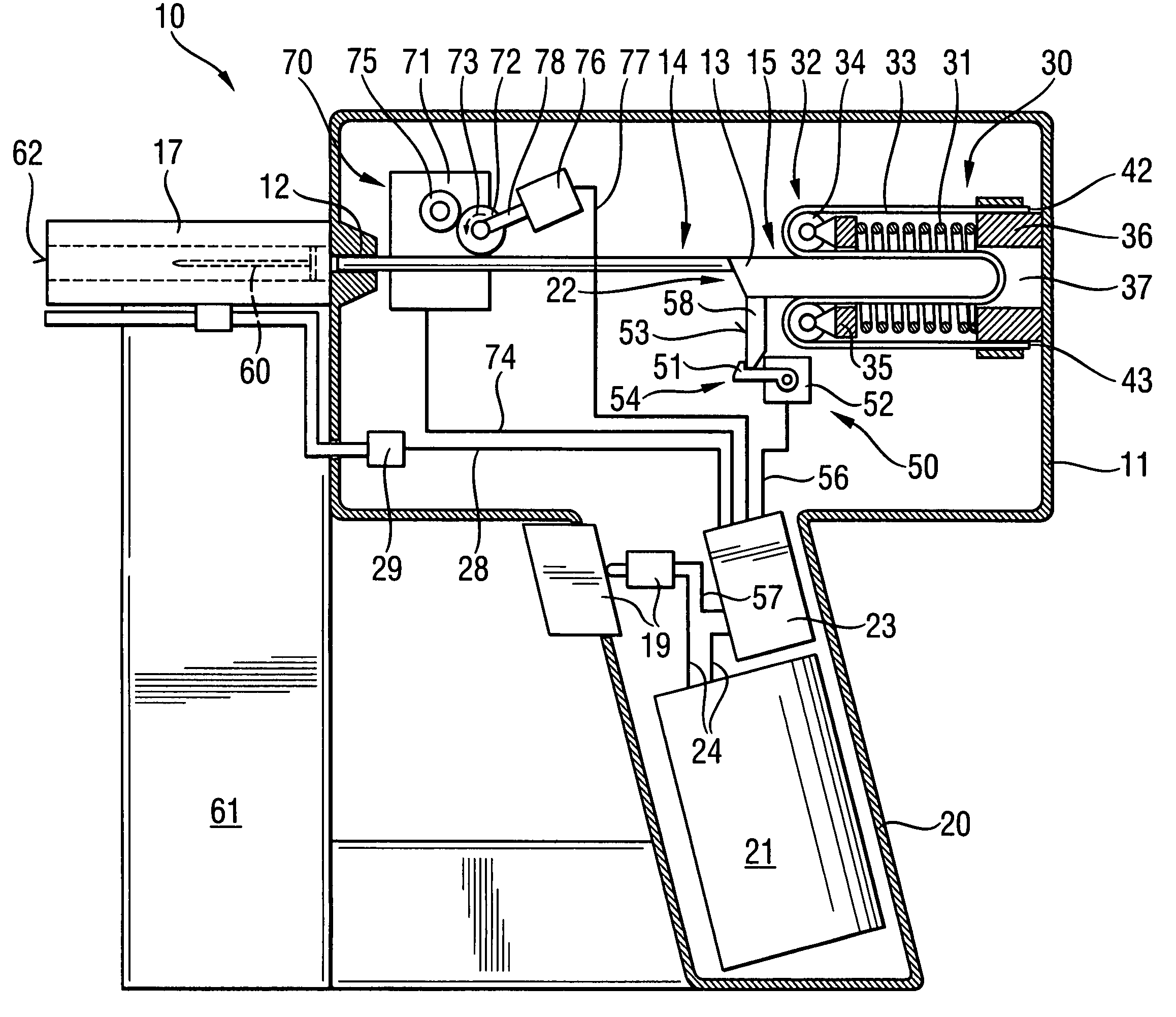
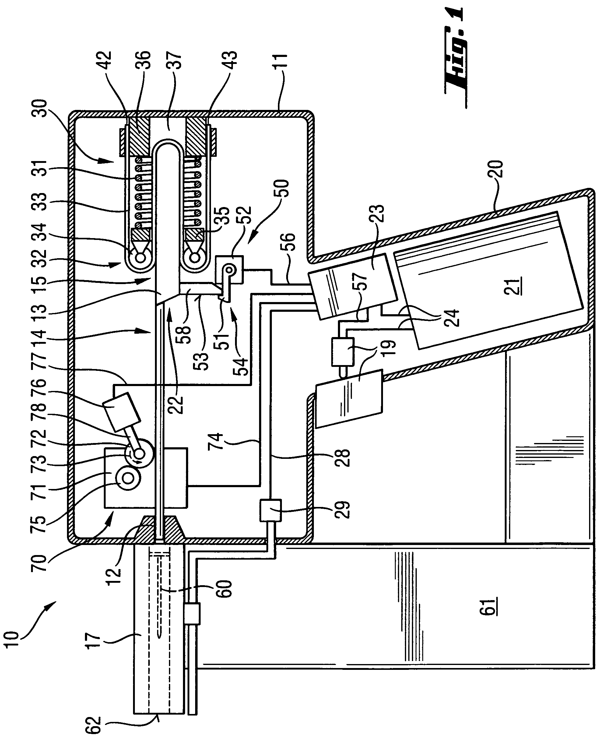
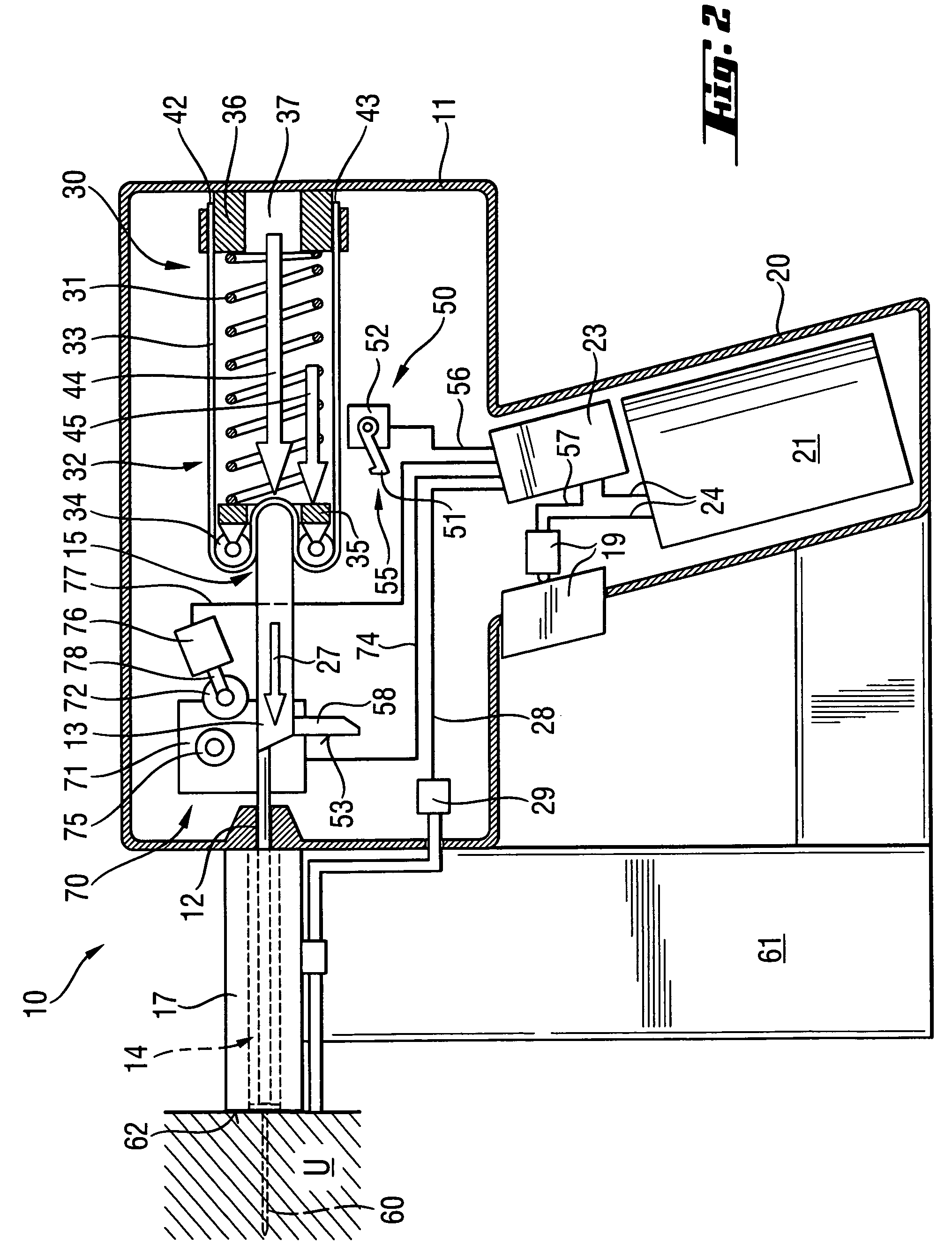
[0021]A power tool 10 according to the present invention, which is shown in FIGS. 1-2, has a housing 11 and located in the housing 11, drive means, which is generally indicated with a reference numeral 30, for driving a drive-in ram 13 displaceable in a guide 12 likewise located in the housing 10. The drive-in ram 13 has a driving section 14 and a head section 15. A bolt guide 17 adjoins an end of the guide 12 facing in the drive-in direction 27 and is arranged coaxially with the guide 12. Sidewise of the bolt guide 17, a magazine 61 for fastening elements is arranged. In the magazine 61, fastening elements 60 are stored.

[0022]The drive means 30 includes a drive spring 31 and a transmission mechanism, which is generally indicated with a reference numeral 32 and which engages the head section 15 of the drive-in ram 13. The driving force generated by the drive spring 31 is transmitted to the drive-in ram 13 via the transmission mechanism 32. The drive spring 31 is formed as a helical ...


PUM

PropertyMeasurementUnit
impact energyaaaaaaaaaa
accelerationaaaaaaaaaa
biasing forceaaaaaaaaaa

Abstract

A hand-held drive-in power tool for driving in fastening elements includes a drive-in ram displaceable in a guide located in the tool housing, a drive for driving the drive-in ram and including at least one preloaded drive spring, a tensioning device for preloading the drive spring, and a transmission mechanism arranged between the drive spring and the drive-in ram.

Description

BACKGROUND OF THE INVENTION[0001]1. Field of the Invention[0002]The present invention relates to a hand-held drive-in power tool for driving in fastening elements and including a guide, a drive-in ram displaceable in the guide, drive means for driving the drive-in ram and including at least one preload drive spring, and a tensioning device for preloading the drive spring.[0003]2. Description of the Prior Art[0004]Hand-held power tools of the type described above are used for driving fastening elements in a constructional component with the ram. The drive spring serves as a driving source and is preloaded by a tensioning device. The advantage of the above-described tool consists in that the mechanical drive spring can be economically produced which permits to insure a cost-effective manufacturing of the entire power tool. Further, an advantage of mechanical springs over gas springs in general consists in that upon preloading of a mechanical spring, the temperature does not increase a...

Claims


Application Information

Patent Timeline
Patent Type & Authority Patents(United States)
IPC IPC(8): B25C1/06
CPCB25C1/06
Inventor SCHIESTL, ULRICH
Owner HILTI AG
Why Eureka
Try Eureka