Bicycle wheel securing structure

a technology for bicycle wheels and securing structures, which is applied in the direction of rod connections, cycle equipment, release mechanisms, etc., can solve the problems of difficult for some individuals to tighten such a knob, other bicycle parts such as bicycle wheels need to be loosened and removed, etc., and achieves the effect of tight connection and easy tightening

Active Publication Date: 2009-05-26
SHIMANO INC
View PDF17 Cites 47 Cited by
  • Summary
  • Abstract
  • Description
  • Claims
  • Application Information

AI Technical Summary

Benefits of technology

[0009]One object of the present invention is to provide a bicycle wheel securing structure, which provides a tight connection, yet is relatively easy to tighten.
[0010]Another object of the present invention is to provide a bicycle wheel securing structure, which is relatively simple and inexpensive to manufacture and / or assemble.

Problems solved by technology

However, while certain bicycle parts are designed to be permanently attached to the bicycle, other bicycle parts such as bicycle wheels need to be loosened and removed relatively often.
However, it can be difficult for some individuals to tighten such a knob.

Method used


Image

  • Bicycle wheel securing structure
  • Bicycle wheel securing structure
  • Bicycle wheel securing structure

Examples


second embodiment

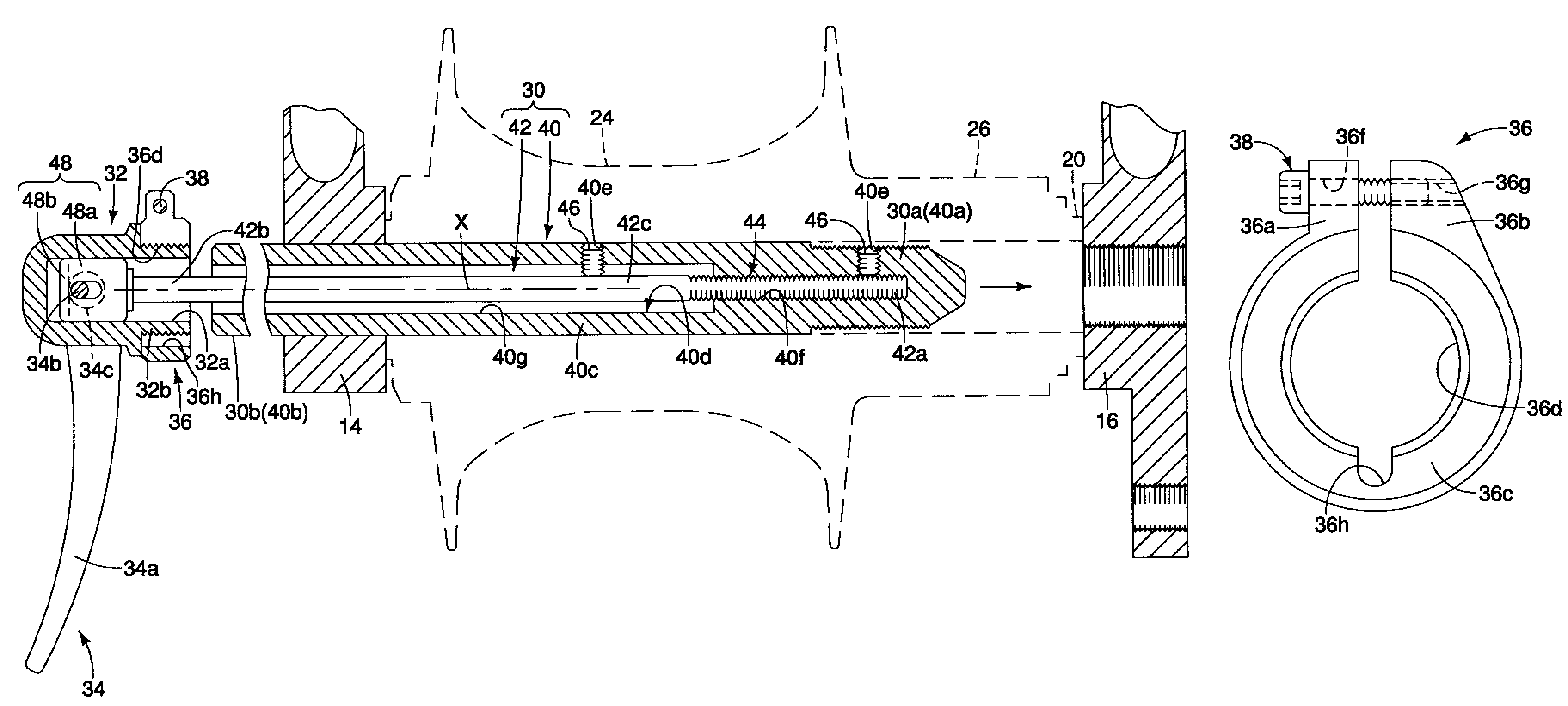
[0068]Referring now to FIG. 14, a wheel securing axle 222 having a modified shaft member 230 with a modified outer axle 240 in accordance with a second embodiment of the present invention will now be explained. The wheel securing axle 222 of this second embodiment is identical to the wheel securing axle 22 of the first embodiment, except for the outer axle 240 of the shaft member 230. Accordingly, this second embodiment will not be discussed and / or illustrated in detail herein, except as related to the outer axle 240. However, it will be apparent to those skilled in the bicycle art from this disclosure that the descriptions and illustrations of the first embodiment also apply to this second embodiment, except as explained and / or illustrated herein. Moreover, it will be apparent to those skilled in the bicycle art from this disclosure that the wheel securing axle 222 is designed to replace the wheel securing axle 22 of the first embodiment to mount the unit including the main hub axl...

third embodiment

[0071]Referring now to FIG. 15, mounting the rear hub 12 with the wheel securing axle 22 of the first embodiment to a modified mounting flange 316 in accordance with a third embodiment of the present invention will now be explained. The mounting flange 316 of this third embodiment is identical to the mounting flange 16 of the first embodiment, except the mounting flange 316 includes a larger, unthreaded opening 316a with an adapter 317 received therein. Accordingly, this third embodiment will not be discussed and / or illustrated in detail herein, except as related to the mounting flange 316 and the adapter 317. However, it will be apparent to those skilled in the bicycle art from this disclosure that the descriptions and illustrations of the first embodiment also apply to this third embodiment, except as explained and / or illustrated herein. Moreover, it will be apparent to those skilled in the bicycle art from this disclosure that mounting flange 316 with the adapter 317 is designed ...

fourth embodiment

[0074]Referring now to FIGS. 16 and 17, a wheel securing axle 422 having a modified shaft member 430 in accordance with a fourth embodiment of the present invention will now be explained. The wheel securing axle 422 of this fourth embodiment is identical to the wheel securing axle 22 of the first embodiment, except for the shaft member 430. Accordingly, this fourth embodiment will not be discussed and / or illustrated in detail herein, except as related to the shaft member 430. However, it will be apparent to those skilled in the bicycle art from this disclosure that the descriptions and illustrations of the first embodiment also apply to this fourth embodiment, except as explained and / or illustrated herein. Moreover, it will be apparent to those skilled in the bicycle art from this disclosure that the wheel securing axle 422 is designed to replace the wheel securing axle 22 of the first embodiment to mount the unit including the main hub axle 20, the hub assembly 24 and the free whee...


PUM


Abstract

A bicycle wheel securing structure includes a shaft member, a head member, a lever member and an adjustment member. The shaft member has a first threaded end and a second end with a center axis extending therebetween. The head member is disposed on the second end of the shaft member. The lever member is operatively mounted between the shaft member and the head member to move the shaft member in an axial direction relative to the head member in response to movement of the lever member. The adjustment member is axially adjustably coupled to the head member such that an axial position of an abutment surface of the adjustment member can be adjusted relative to the shaft member.

Description

BACKGROUND OF THE INVENTION[0001]1. Field of the Invention[0002]This invention generally relates to a bicycle wheel securing structure. More specifically, the present invention relates to a bicycle wheel securing structure, which includes an adjustment member that is axially adjustable relative to the head member.[0003]2. Background Information[0004]Bicycling is becoming an increasingly more popular form of recreation as well as a means of transportation. Moreover, bicycling has become a very popular competitive sport for both amateurs and professionals. Whether the bicycle is used for recreation, transportation or competition, the bicycle industry is constantly improving the various components of the bicycle. One component that has been extensively redesigned is the bicycle quick release mechanism.[0005]In the past various bicycle parts have been attached using nut and bolt arrangements. However, while certain bicycle parts are designed to be permanently attached to the bicycle, ot...

Claims


Application Information

Patent Timeline
Patent Type & Authority Patents(United States)
IPC IPC(8): B60B35/00
CPCB60B27/026B60B35/004B60B35/04B62K25/02Y10T403/7064B62K2206/00Y10T403/7071
Inventor HARA, NOBUKATSU
Owner SHIMANO INC
Why Eureka
Try Eureka