Coordinate input apparatus, control method thereof, and program
a technology of input apparatus and control method, applied in the field of coordinate input apparatus, can solve the problems of inability to accurately detect input coordinates, affecting the accuracy of input coordinates, and reducing the light intensity of instruments, etc., and achieve the effect of accurately detecting input coordinates
- Summary
- Abstract
- Description
- Claims
- Application Information
AI Technical Summary
Benefits of technology
Problems solved by technology
Method used
Image
Examples
first embodiment
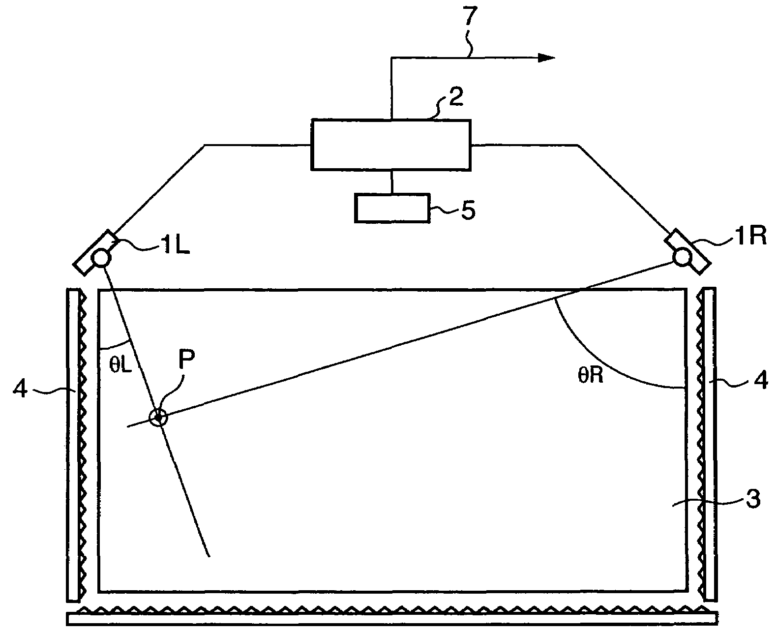
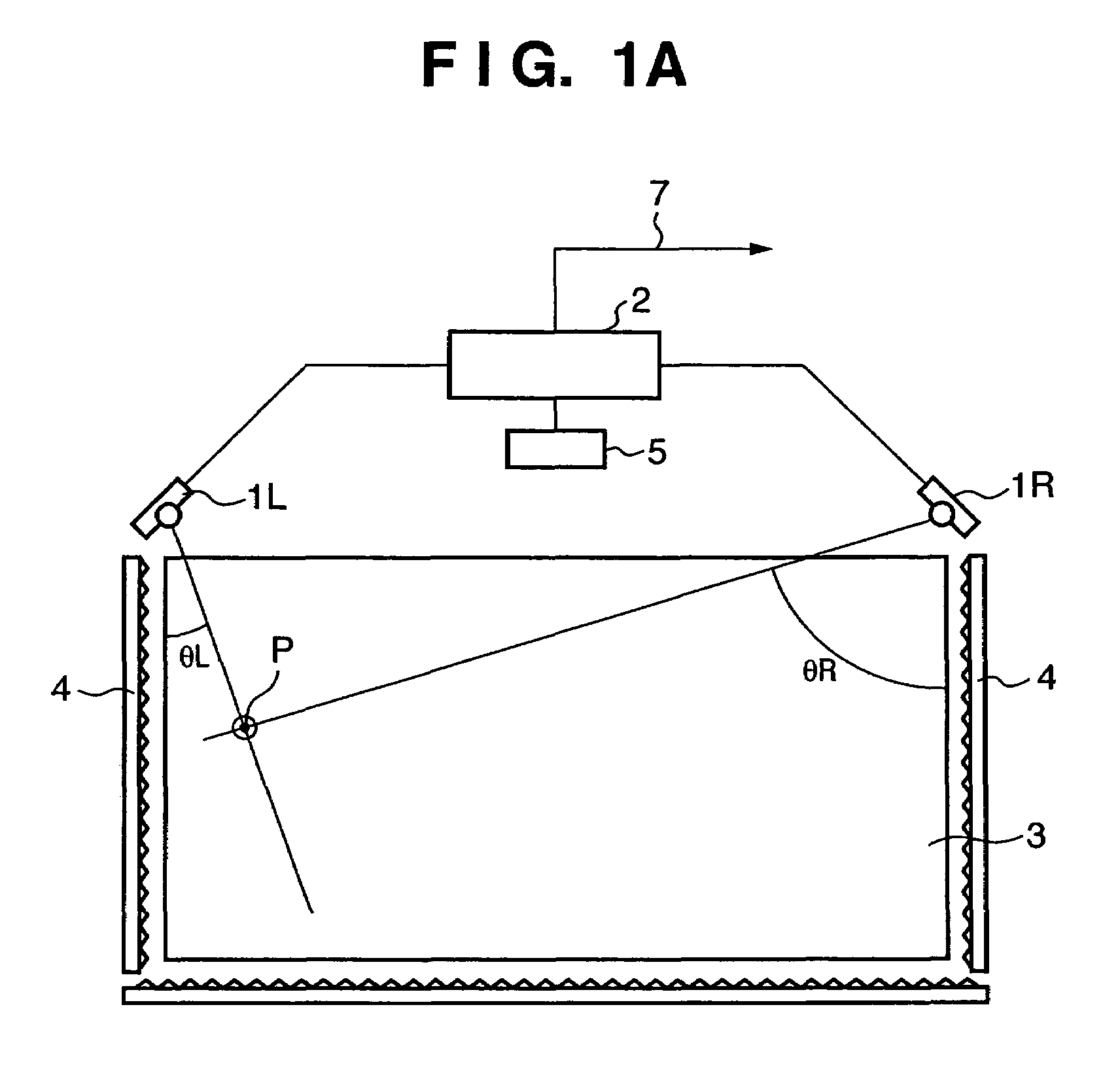
[0204]FIG. 1A is a view showing the arrangement of a coordinate input apparatus of light shielding scheme according to the first embodiment of the present invention.
[0205]Referring to FIG. 1A, sensor units 1L and 1R have light projecting units and light receiving units. In the first embodiment, the sensor units 1L and 1R are arranged parallel to the X-axis of a coordinate input effective region 3 serving as a coordinate input surface and symmetrically about the Y-axis while being spaced apart by a predetermined distance, as shown in FIG. 1A. The sensor units 1L and 1R are connected to a control / arithmetic unit 2. Each of the sensor units 1L and 1R receives a control signal from the control / arithmetic unit 2 and transmits a detected signal to the control / arithmetic unit 2.
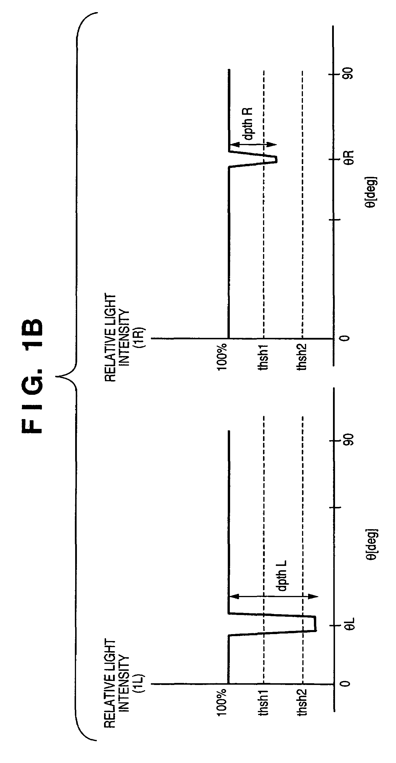
[0206]A retroreflecting member 4 has a retroreflecting surface to reflect incident light in the direction of arrival. The retroreflecting member 4 is arranged on three outer sides of the coordinate input effective r...
second embodiment
[0300]FIG. 13 is a view showing the arrangement of a coordinate input apparatus of light shielding scheme according to the second embodiment of the present invention.
[0301]The basic arrangement of the coordinate input apparatus shown in FIG. 13 is the same as that of the coordinate input apparatus shown in FIG. 1A. In the first embodiment, the detailed arrangement of the sensor units 1L and 1R have not been described particularly. This will be described in the second embodiment.
[0302]Each of the sensor units 1L and 1R of the first embodiment incorporates one set of a light projecting unit and a light receiving unit. In the second embodiment shown in FIG. 13, each of sensor units 1L and 1R includes two sets of light projecting units and light receiving units. That is, the first embodiment employs a single-lens structure in which one optical unit is incorporated in one sensor unit. However, the second embodiment employs a multiple-lens (twin-lens) structure in which two optical units ...
third embodiment
[0406]In the third embodiment, an arrangement will be described in which a sensor unit 1C is newly added to the arrangement of the first embodiment shown in FIG. 1A, as shown in FIG. 30.
[0407]FIG. 30 shows multiple point input in points P12 and P21.
[0408]In this case, as shown in FIG. 31A, a sensor unit 1L detects shadows at positions θL1 and θL2. As shown in FIG. 31B, a sensor unit 1R detects shadows at positions θR1 and θR2. As shown in FIG. 31C, the sensor unit 1C detects shadows at positions θC1 and θC4. On the basis of the three sets of angle data, four coordinate candidate points P11, P12, P21, and P22 are calculated. When truth determination is executed for these coordinate candidate points by a certain means, for example, P11 and P22 are determined as real images, and P12 and P21 are determined as virtual images. Hence, the coordinate input points can be decided.
[0409]The sensor unit 1C shown in FIG. 30 has almost the same arrangement as the sensor unit 1L or 1R except the s...
PUM
 Abstract
Description
Claims
Application Information
 - R&D
- Intellectual Property
- Life Sciences
- Materials
- Tech Scout
- Unparalleled Data Quality
- Higher Quality Content
- 60% Fewer Hallucinations
Browse by: Latest US Patents, China's latest patents, Technical Efficacy Thesaurus, Application Domain, Technology Topic, Popular Technical Reports.
© 2025 PatSnap. All rights reserved.Legal|Privacy policy|Modern Slavery Act Transparency Statement|Sitemap|About US| Contact US: help@patsnap.com


