Apparatus for adjustable bead retention on bracelets and necklaces

a technology of adjustable beads and beads, which is applied in the field of bracelets and necklaces, can solve the problems of unlikely unintended movement of the adjustable beads, and achieve the effects of reducing the cost of fabricating the beads, increasing friction, and high surface tension

Inactive Publication Date: 2009-06-02
CHAMILIA
View PDF42 Cites 30 Cited by
  • Summary
  • Abstract
  • Description
  • Claims
  • Application Information

AI Technical Summary

Benefits of technology

[0012]It is an object of the present invention to provide a modifiable bracelet, necklace, or other removable jewelry item configured to enable a wearer to easily add and remove supplemental pieces to the item strand. It is also an object of the present invention to provide such a modifiable jewelry item configured to enable a wearer to position selectively on the strand one or more retainers to retain one or more supplemental pieces on the strand. Further, it is an object of the present invention to provide such a modifiable jewelry item including end connectors suitable for ease of passage of retainers and / or supplemental pieces thereover.
[0013]These and other objects are achieved with the present invention, which is a modifiable jewelry item including one or more adjustable retainers. The adjustable retainer may be a unitary piece configured to slide onto the strand, chain, or band of the jewelry item. Alternatively, the adjustable retainer may be formed of two parts, possibly hinged, and arranged to be placed about the strand and removably clasped in place thereon. The adjustable retainer of the jewelry item includes an interior structure that keeps the retainer in a selectable position on the strand.
[0014]The interior structure is configured to establish high-friction contact between the retainer and the strand. The friction between the interior of the retainer and the strand may be selectable and a function of the details of the interior structure and the outer surface of the strand. The interior structure may be arranged by itself, or in combination with the arrangement of the outer surface of the strand, to be frictional enough to require substantial force to dislodge the adjustable retainer from its particular position on the strand. Alternatively, the interior structure may be arranged to allow relative ease of movement along the strand, but with enough friction that unintended movement of the adjustable retainer is unlikely to occur. Nevertheless, the interior structure is arranged to cover substantially all of the inside dimensions of the adjustable retainer such that substantially all of the interior structure is in contact with the stand when the retainer is positioned on the stand. The arrangement of the interior structure as well as its frictional characteristics substantially restrict movement of the retainer along the strand and rotational movement of the retainer around the strand when the retainer is positioned on the strand.

Problems solved by technology

Alternatively, the interior structure may be arranged to allow relative ease of movement along the strand, but with enough friction that unintended movement of the adjustable retainer is unlikely to occur.

Method used


Image

  • Apparatus for adjustable bead retention on bracelets and necklaces
  • Apparatus for adjustable bead retention on bracelets and necklaces
  • Apparatus for adjustable bead retention on bracelets and necklaces

Examples


first embodiment

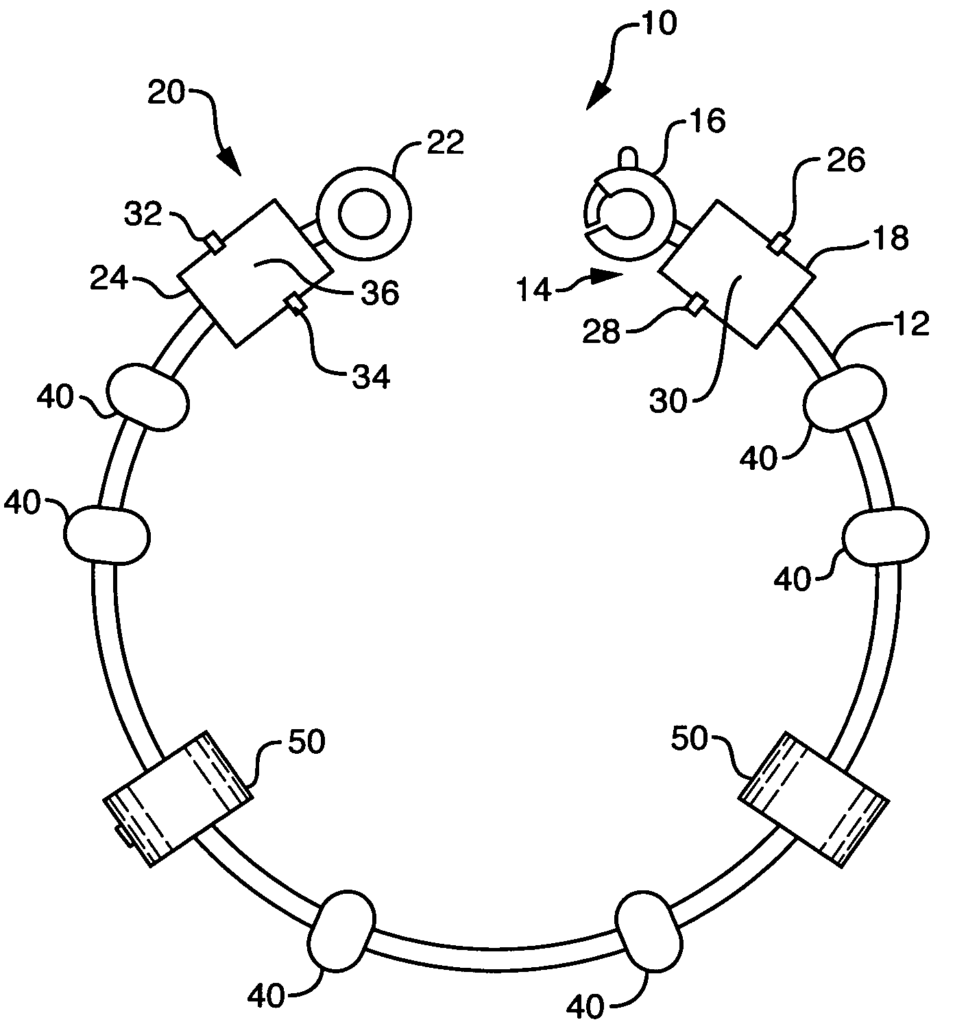
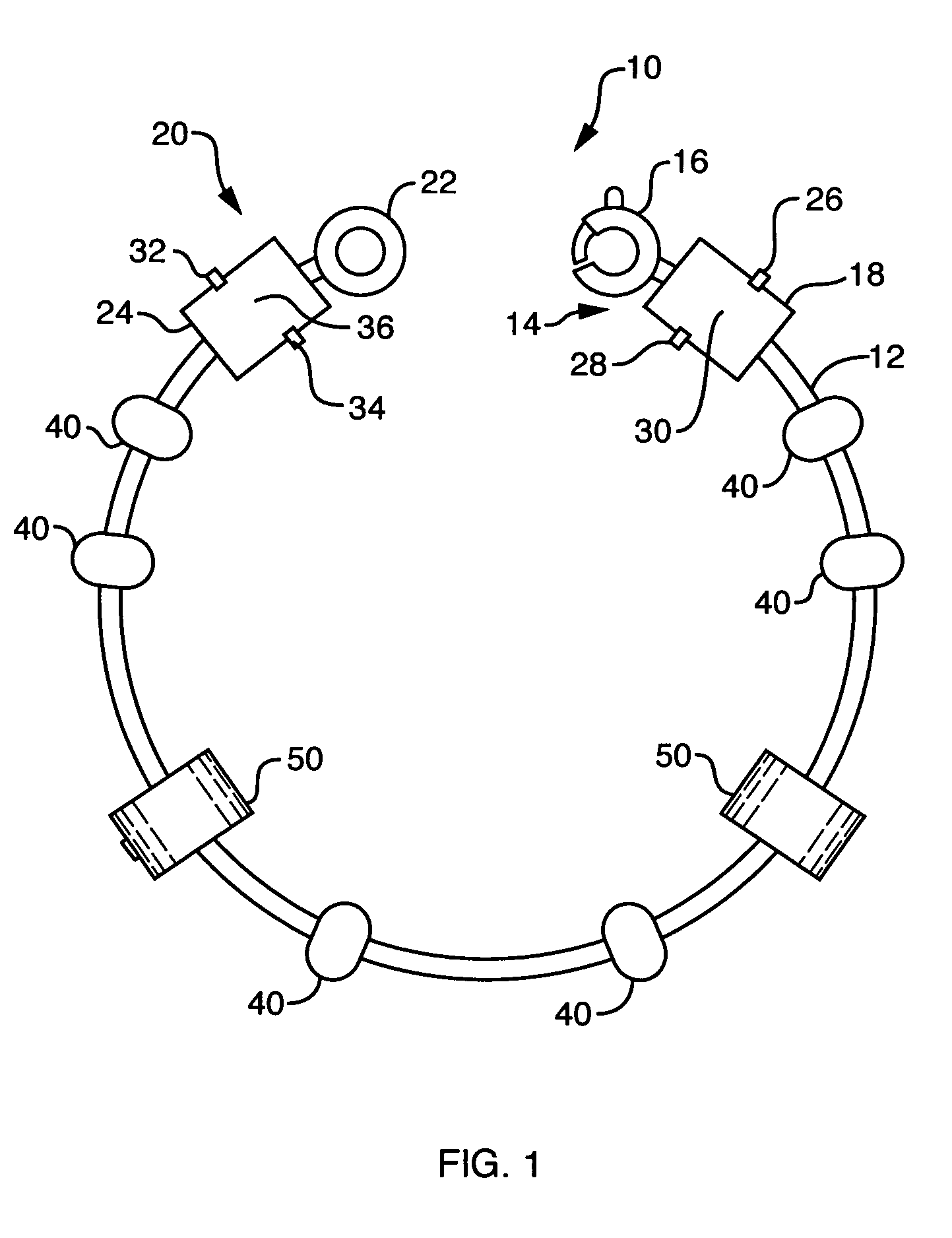
[0032]As illustrated in FIG. 2, the adjustable retainer 50 is a unitary annular ring or bushing fabricated of a selectable material. The unitary adjustable retainer 50 includes an interior structure 52 that may cover a portion or substantially all of the inside dimensions of the adjustable retainer 50. The interior structure 52 is configured to enhance frictional contact between the adjustable retainer 50 and the outer surface of the strand 12. The interior structure may be configured with selectable frictional characteristics. That is, it may be formed to make movement of the adjustable retainer 50 on the strand 12 relatively difficult or relatively simple. A relatively high coefficient of friction of the interior structure 52 makes movement of the adjustable retainer 50 on the strand 12 relatively difficult and would be useful to the wearer who wishes to have little unintended movement of the adjustable retainer 50 on the strand 12. A relatively low coefficient of friction of the ...

second embodiment

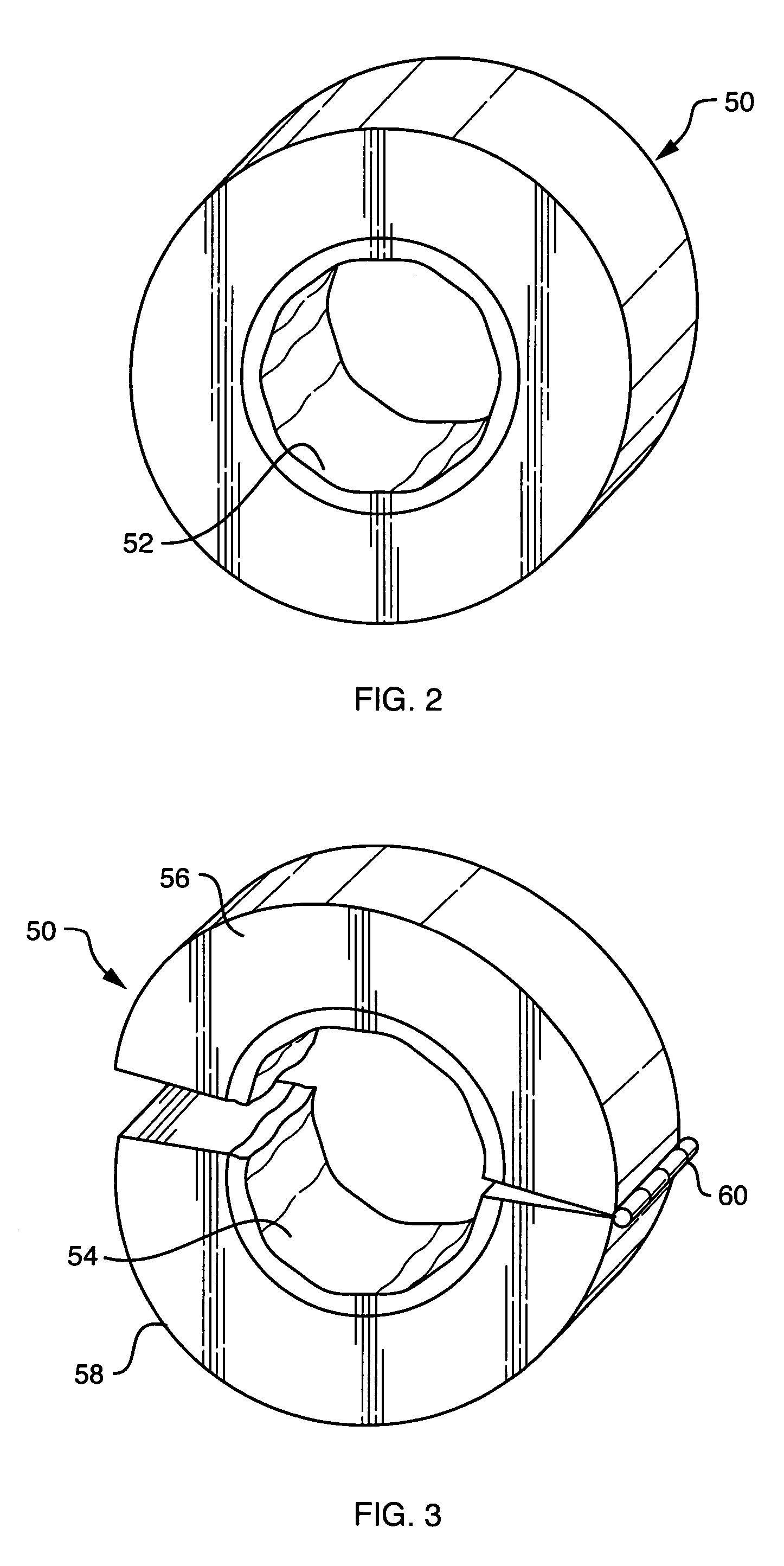
[0033]As illustrated in FIG. 3, the adjustable retainer 50 is a hinged annular ring or bushing fabricated of a selectable material. The hinged adjustable retainer 50 includes an interior structure 54 that may cover a portion or substantially all of the inside dimensions of the adjustable retainer 50. The hinged adjustable retainer 50 further includes a first piece 56, a second piece 58, and a hinge joint 60 hingedly connecting the two. As with the interior structure 52 of unitary adjustable retainer 50 of FIG. 2, the interior structure 54 is configured to enhance frictional contact between the adjustable retainer 50 and the outer surface of the strand 12. The interior structure may be configured with selectable frictional characteristics as described with respect the interior structure 52 of FIG. 2. The first piece 56 and the second piece 58 preferably including a latching mechanism or locking mechanism, such as a pressure fit tongue-and-groove arrangement for releasable clamping of...


PUM


Abstract

A modifiable jewelry piece including a strand and one or more adjustable retainers. The adjustable retainers include an interior structure configured to establish a frictional engagement with the outer surface of the strand. The jewelry piece wearer may select the location of the placement of the adjustable retainer anywhere along the length of the strand. The interior structure may be a solid or semi-solid having high surface tension or rough surface profile. The interior structure may alternatively be a mechanical capturing device. The jewelry piece also includes one or two end connectors having a slot and flange arrangement for easy passage of beads thereover only when desired. The flange and slot are arranged for alignment with threaded and flanged beads.

Description

BACKGROUND OF THE INVENTION[0001]1. Field of the Invention[0002]The present invention relates to bracelets and necklaces. More particularly, the present invention relates to bracelets and necklaces arranged to enable a wearer to change beads and adjust the positioning of beads thereon. Still more particularly, the present invention relates to bracelets and necklaces including adjustable means for bead position retention. The present invention also includes an improved end connector arrangement to facilitate bead placement on bracelets and necklaces.[0003]2. Description of the Prior Art[0004]Jewelry bracelets and necklaces of the type having two end connectors or clasps, allow the wearer to place the jewelry around the wrist or neck, secure it in position, and be reasonably assured that it will not pass over the hand or head. Such jewelry is generally formed as a strand, chain or band with the end connectors or clasps at opposing ends thereof. The end connectors may be joined togethe...

Claims


Application Information

Patent Timeline
Patent Type & Authority Patents(United States)
IPC IPC(8): A44C5/00A44C25/00
CPCA44C5/0053A44C11/002A44C15/005A44C25/001
Inventor JULKOWSKI, JEFFSERGENT, TROY
Owner CHAMILIA
Why Eureka
Try Eureka