Winding mechanism for a window blind

a technology of window blinds and winding mechanisms, which is applied in the direction of door/window protective devices, web handling, transportation and packaging, etc., can solve the problems of affecting the winding and unwinding action of the lift cord, not being able to move easily, and being easily jammed, so as to prevent the jamming of the guide seat. , the effect of easy and smooth operation

Inactive Publication Date: 2009-06-02
CHEN KUO HUA
View PDF18 Cites 20 Cited by
  • Summary
  • Abstract
  • Description
  • Claims
  • Application Information

AI Technical Summary

Benefits of technology

[0008]The primary objective of the present invention is to provide a winding mechanism that is operated easily and smoothly.
[0009]Another objective of the present invention is to provide a winding mechanism for a window blind, wherein when the lift cord is wound around the rotation member, the guide seat is movable successively on the rotation member by guidance of the roller, so that the lift cord is wound around the rotation member serially and smoothly by guidance of the guide seat, thereby preventing the lift cord from being tangled.
[0010]A further objective of the present invention is to provide a winding mechanism for a window blind, wherein the lift cord is extended through and guided by the guide groove of the roller, so that the lift cord is moved smoothly, and the guide seat is also moved smoothly.
[0011]A further objective of the present invention is to provide a winding mechanism for a window blind, wherein when the guide seat is movable to the outermost portion the rotation member, a further movement of the guide seat is stopped by the first end cap and the second end cap respectively, thereby preventing the guide seat from being jammed due to an excessive force applied on the guide seat.

Problems solved by technology

However, the limit rod 14 provides a resistance to the guide disk 12 during the axial movement of the guide disk 12, so that the guide disk 12 is not moved easily and smoothly, thereby affecting the winding and unwinding action of the lift cord 20.
In addition, when the guide disk 12 is movable to the outermost portion the threaded rod 11, the guide disk 12 is easily jammed due to an excessive force applied on the guide disk 12, thereby affecting or failing operation of the winding mechanism.

Method used


Image

  • Winding mechanism for a window blind
  • Winding mechanism for a window blind
  • Winding mechanism for a window blind

Examples


Embodiment Construction

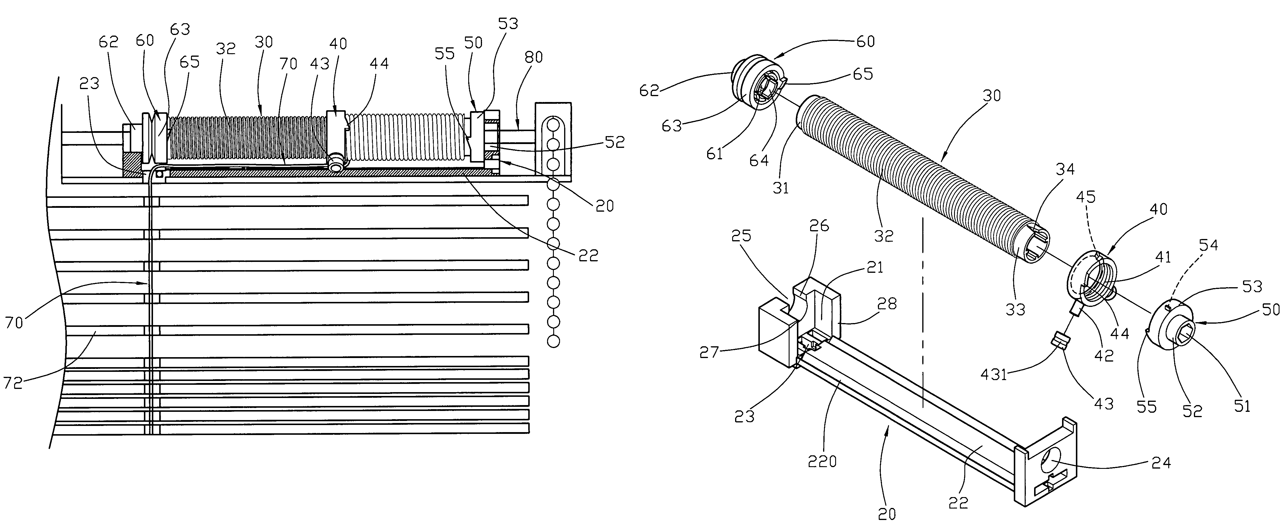
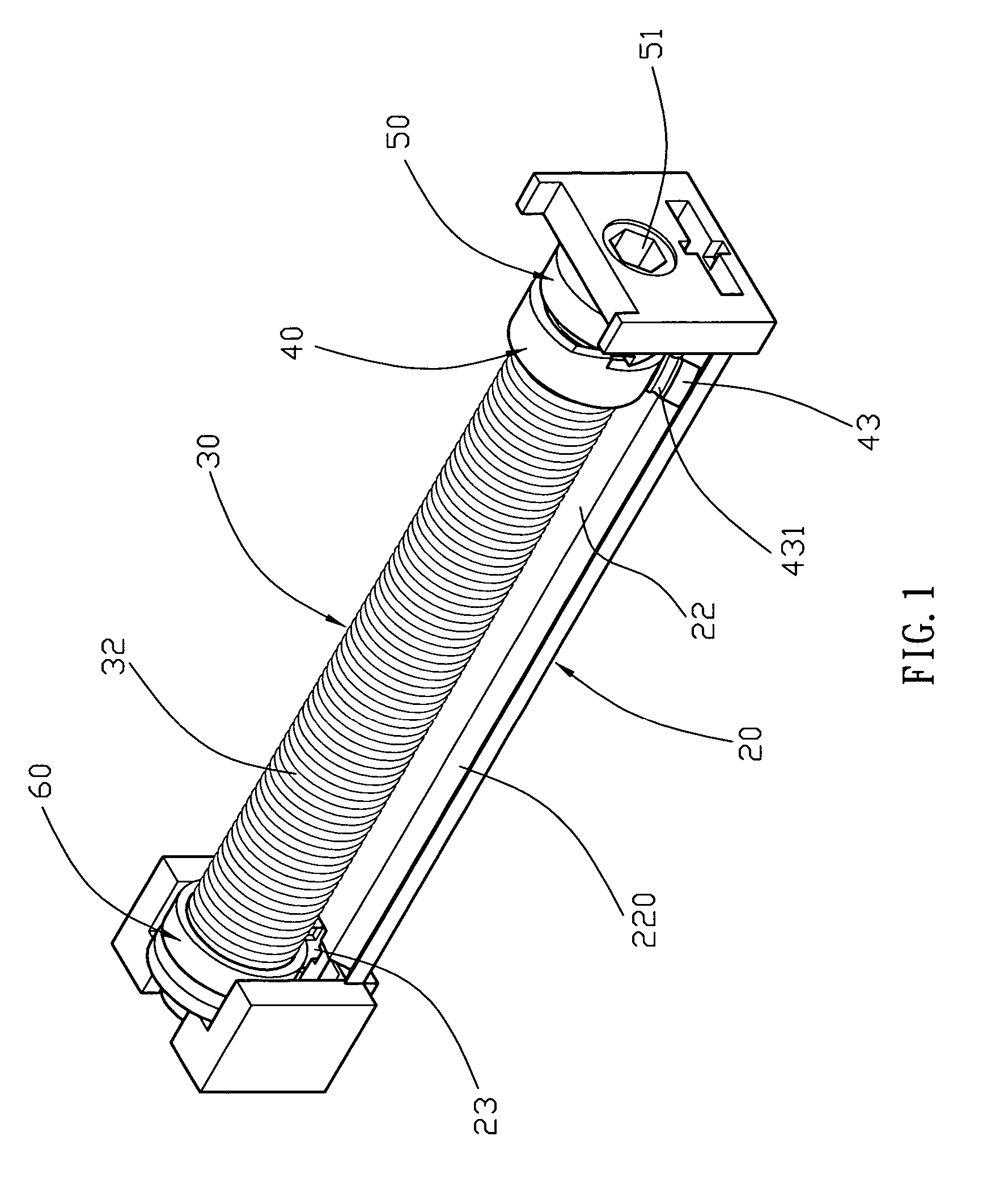
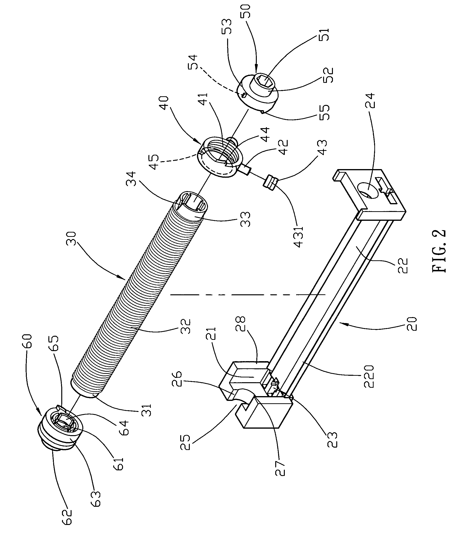
[0023]Referring to the drawings and initially to FIGS. 1-5, a winding mechanism for a window blind in accordance with the preferred embodiment of the present invention comprises a base 20 having a bottom plate 22 formed with two axially extending slideways 220, a rotation member 30 rotatably mounted on the base 20 and having an outer wall formed with an axially extending threaded guide portion 32, a guide seat 40 having an inner wall formed with a threaded guide hole 41 screwed onto the threaded guide portion 32 of the rotation member 30 and an outer wall formed with two protruding guide posts 42 each provided with at least one roller 43 slidably mounted in a respective slideway 220 of the base 20 so that the guide seat 40 is axially movable on the rotation member 30 by guidance of the guide posts 42 and is not rotatable with the rotation member 30 when the rotation member 30 is rotatable relative to the base 20, a first end cap 50 secured to a first end 33 of the rotation member 30...


PUM


Abstract

A winding mechanism for a window blind includes a base having two slideways, a rotation member rotatably mounted on the base and having an outer wall formed with a threaded guide portion, and a guide seat having an inner wall formed with a threaded guide hole screwed onto the threaded guide portion of the rotation member and an outer wall formed with two guide posts each provided with a roller slidably mounted in a respective slideway of the base. Thus, when the lift cord is wound around the rotation member, the guide seat is movable successively on the rotation member by guidance of the roller, so that the lift cord is wound around the rotation member serially and smoothly by guidance of the guide seat, thereby preventing the lift cord from being tangled.

Description

BACKGROUND OF THE INVENTION[0001]1. Field of the Invention[0002]The present invention relates to a winding mechanism and, more particularly, to a winding mechanism for a window blind.[0003]2. Description of the Related Art[0004]A conventional winding mechanism for a window blind in accordance with the prior art shown in FIGS. 8-10 comprises a base 10 having a hollow inside formed with a receiving chamber 101 and having two opposite end walls each formed with an opening 102 and a locking hole 103, a threaded rod 11 rotatably mounted on the base 10 and having an inside formed with a square drive hole 111, a square drive shaft extended through the drive hole 111 of the threaded rod 11 to rotate the threaded rod 11, a guide disk 12 having an inner wall formed with a threaded guide hole 121 screwed onto the threaded rod 11 and a peripheral wall formed with a limit hole 122, and a limit rod 14 extended through the limit hole 122 of the guide disk 12 and having two ends each secured in the...

Claims


Application Information

Patent Timeline
Patent Type & Authority Patents(United States)
IPC IPC(8): E06B9/30
CPCE06B9/322E06B2009/3225
Inventor CHEN, KUO-HUA
Owner CHEN KUO HUA
Why Eureka
Try Eureka