Abrasive jet cutting system and method for cutting wellbore tubulars

a wellbore and tubular technology, applied in the field of wellbore operations, can solve the problems of difficult to create clean cuts, damage to material behind the cut, and limited cutting depth,

Active Publication Date: 2009-06-02
SCHLUMBERGER TECH CORP
View PDF20 Cites 41 Cited by
  • Summary
  • Abstract
  • Description
  • Claims
  • Application Information

AI Technical Summary

Problems solved by technology

Each of this mechanisms and methods have drawbacks.
For example, with regard to explosive cutters, it is difficult to create clean cuts and to not damage material behind the cut.
Additionally, health and safety concerns dictate strict operational procedures be employed when utilizing explosive cutters.
With regard to chemical cutting tools, the cut depth is limited by the nature of the system and the completion.
With regard to mechanical cutting, when performed using drill pipe or coiled tubing the use of a rig is required; thus increasing time loss and expenses.

Method used


Image

  • Abrasive jet cutting system and method for cutting wellbore tubulars
  • Abrasive jet cutting system and method for cutting wellbore tubulars
  • Abrasive jet cutting system and method for cutting wellbore tubulars

Examples


Embodiment Construction

[0017]Refer now to the drawings wherein depicted elements are not necessarily shown to scale and wherein like or similar elements are designated by the same reference numeral through the several views.

[0018]As used herein, the terms “up” and “down”; “upper” and “lower”; and other like terms indicating relative positions to a given point or element are utilized to more clearly describe some elements of the embodiments of the invention. Commonly, these terms relate to a reference point with the surface from which drilling operations are initiated being the top point and the total depth of the well being the lowest point.

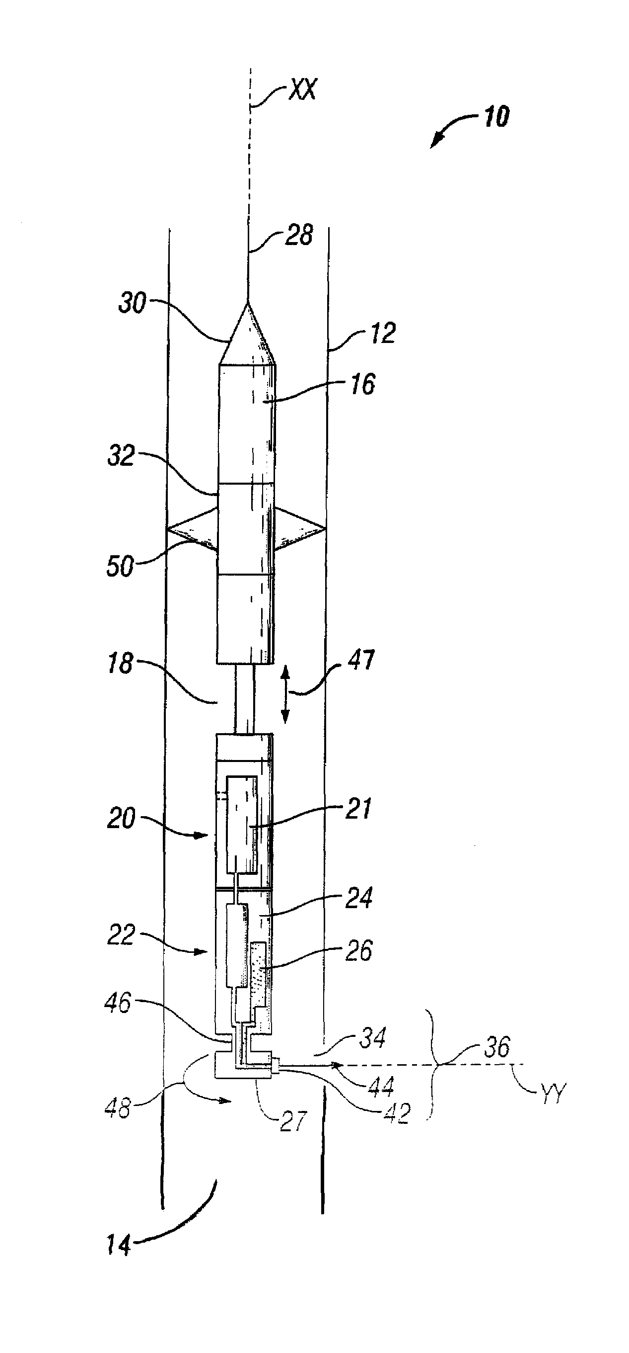
[0019]FIG. 1 is a schematic drawing of an embodiment of an abrasive jet cutting tool of the present invention, generally denoted by the numeral 10. The cutting tool 10 is positioned within a tubular 12 disposed in a wellbore 14 to create a cut 34 in the tubular 12. As will be described in detail herein, the method and system of the present invention can provide linear ...


PUM


Abstract

An embodiment of a cutting tool positionable in a tubular for creating a cut in a tubular includes a body securable within the tubular and a cutting head having a nozzle for discharging a pressurized cutting fluid, wherein the cutting head is rotationally and axially moveable relative to the body. The cutting tool may further include one or more of a positioning mechanism, a linear actuator in connection with the cutting head, a rotary actuator in connection with the cutting head, a cutting fluid pump, a mechanism for mixing a fluid and an abrasive to form the abrasive cutting fluid, and reservoirs for storing the abrasive cutting fluid or for storing a fluid and the abrasive separately.

Description

[0001]This application is a Continuation-in-Part of U.S. patent application Ser. No. 11 / 380,690, filed Apr. 28, 2006.FIELD OF THE INVENTION[0002]The present invention relates in general to wellbore operations and more particularly to systems and methods for cutting tubulars in a wellbore.BACKGROUND[0003]At various stages in a well's life it may be necessary to cut the tubulars used in its construction. This may be required during completion of the well, operation of the well or upon abandonment of the well. Reasons for cutting the pipe include without limitation, cutting a tubular that is stuck in the wellbore, cutting a window for side tracking the present wellbore and cutting fluid pathways.[0004]Prior art methods for making radial cuts include explosive jet cutters, chemical cutters and mechanically cutting with drill pipe or coiled tubing. Each of this mechanisms and methods have drawbacks. For example, with regard to explosive cutters, it is difficult to create clean cuts and t...

Claims


Application Information

Patent Timeline
Patent Type & Authority Patents(United States)
IPC IPC(8): E21B29/06E21B29/00
CPCE21B41/00E21B44/005E21B29/002
Inventor BILLINGHAM, MATTHEW
Owner SCHLUMBERGER TECH CORP
Why Eureka
Try Eureka