Electric device where actuator unit and printed wiring board are connected using bonding parts

a technology of bonding parts and actuators, applied in the direction of printed circuit boards, printed element electric connection formation, dielectric characteristics, etc., can solve the problems of short circuit between individual electrodes, electrical disconnection, and deterioration of the bonding strength between the pad and the auxiliary electrode portion, so as to prevent the occurrence of short circuit, simplify the structure of the electric device, and prevent damage to the actuator unit

Active Publication Date: 2009-06-02
BROTHER KOGYO KK
View PDF16 Cites 4 Cited by
  • Summary
  • Abstract
  • Description
  • Claims
  • Application Information

AI Technical Summary

Benefits of technology

[0009]The present invention has been developed in view of the above-described situations, and it is an object of the invention to provide an electric device in which an actuator unit and a printed wiring board are connected by bonding parts, and which inhibits occurrence of a short-circuit between electrodes due to a contact between bumps of solder or other conductive materials, while simplifying a structure of the electric device, or apparatus using the electric device, and preventing damage of the actuator unit.
[0011]According to this arrangement, the bonding part functions to hold the state where the conducting layer on the protrusion contacts the electrode. Thus, the volume of the conductive material used to maintain the contact between the conducting layer and the electrode can be reduced. Hence, an occurrence of a short-circuit between the electrodes due to a contact between two adjacent bumps of a conductive material can be inhibited. Further, since the state where the conducting layer on the protrusion contacts the electrode is held by the bonding part, an external force required for holding this state can be provided by a relatively simple structure such that the bonding part completely covers the contact portion therebetween, or the contact portion is surrounded by the bonding part, which structure does not require any additional member which would otherwise make the structure of the electric device or the apparatus using the electric device complex. Thus, it is enabled to simplify the structure of the electric device or apparatus as well as inhibit damage of the actuator unit even when the mechanical strength thereof is low.

Problems solved by technology

This leads to a contact between adjacent two solder bumps each connecting the pad and the auxiliary electrode portion, causing a short-circuit between the individual electrodes.
However, this now deteriorates the strength of the bond between the pad and the auxiliary electrode portion, causing an electrical disconnection due to separation of the pad from the auxiliary electrode portion.
Although it is possible to electrically connect an FPC with a piezoelectric patch without using solder in this way, such an arrangement requires additional members to press the FPC against the piezoelectric patch, namely, the elastic member, fixing member, etc., making the structure of the head unit or apparatus using the head unit relatively complex.
Further, the arrangement where the protrusions of the terminals of the FPC are kept pressed onto the piezoelectric patches by the pressing force of the elastic member and fixing member leads to damage of the piezoelectric patch having a low mechanical strength.

Method used


Image

  • Electric device where actuator unit and printed wiring board are connected using bonding parts
  • Electric device where actuator unit and printed wiring board are connected using bonding parts
  • Electric device where actuator unit and printed wiring board are connected using bonding parts

Examples


first embodiment

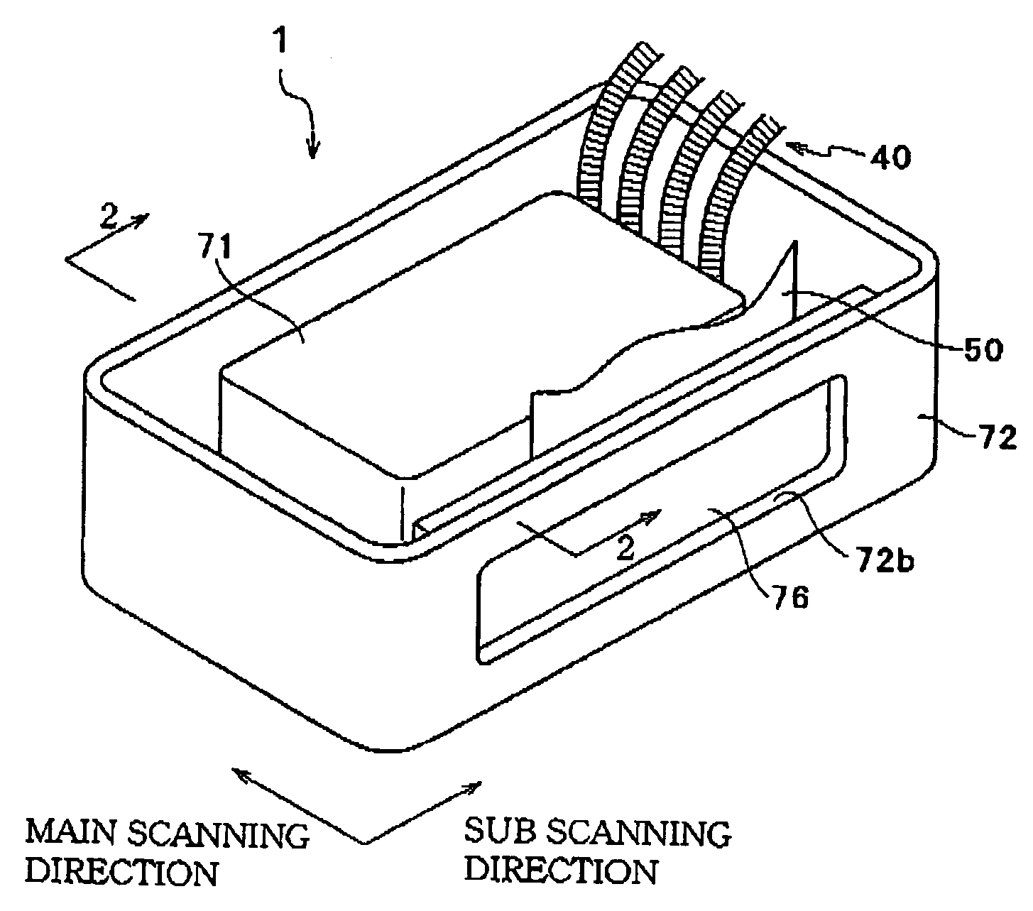
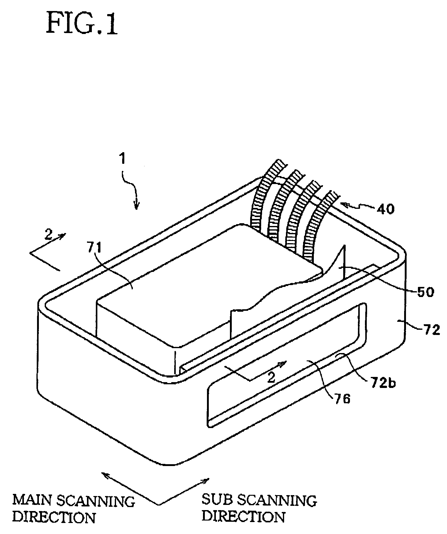
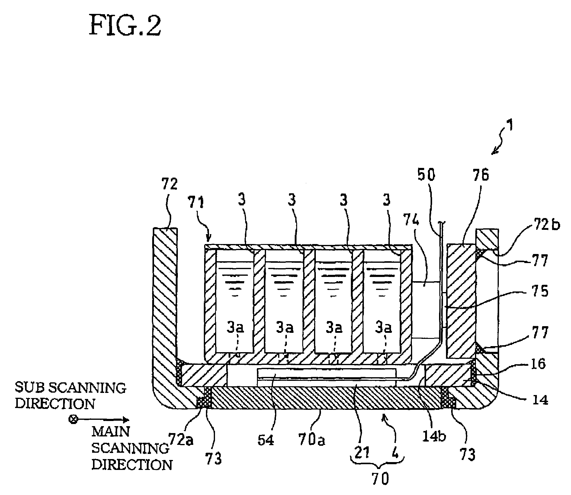
[0039]FIG. 1 is an external perspective view of an inkjet head unit according to a first embodiment of the invention. FIG. 2 is a cross-sectional view taken along a line 2-2 in FIG. 1, showing a state where a printhead is mounted on a holder as a component of the inkjet head unit. FIG. 3 is a perspective view showing a state where a reinforcing plate is bonded to the printhead shown in FIG. 2.

[0040]An inkjet head unit 1 is used in a serial inkjet printer (not shown), and constructed to perform recording by ejecting inks of four colors (cyan, magenta, yellow, and black) onto a recording sheet which is fed in along a sub scanning direction. As shown in FIGS. 1 and 2, the head unit 1 comprises an ink tank 71 in which four compartments 3 for separately storing the four color inks are defined, a printhead 70 disposed below the ink tank 71, and a flexible printed wiring board or a flexible printed circuit board (FPC) 50 attached to the printhead 70.

[0041]In the ink tank 71, the four compa...

second embodiment

[0102]Referring now to FIG. 14, there will be described an FPC 100 of an inkjet head unit according to a second embodiment of the invention. FIG. 14 is a cross-sectional view showing the FPC 100 in enlargement. The elements or parts identical with those of the first embodiment will be denoted by the same reference numerals and description thereof is dispensed with.

[0103]The head unit of the second embodiment has substantially the same structure as the head unit 1 of the first embodiment, but the structure of the FPC 100 is slightly different from that of the FPC 50 in the first embodiment. As shown in FIG. 14, the FPC 100 of the second embodiment has a supporting plate (supporting layer) 101 disposed on an upper surface of a base film 46 (i.e., a side of the base film 46 opposite to the side on which terminals 48a and wires 48b are formed). The other part of the FPC 100 is identical with the FPC 50 as described above.

[0104]The supporting plate 101 is a metallic sheet conforming to t...

third embodiment

[0106]As shown in FIG. 15, the FPC 200 of the third embodiment is configured such that each closed space 102 as described with respect to the second embodiment is filled with an elastic material 202. According to this arrangement, terminals 48a on the FPC 200 have an increased elastic restoring force compared to that of the terminals 48a in the FPC 100 of the second embodiment. Thus, the reliability of the electrical connection between the terminals 48a and lands 36 is further enhanced.


PUM


Abstract

There is disclosed an electric device comprising: an actuator unit which includes a plurality of electrodes formed thereon; a printed wiring board which comprises: an electrically insulating flexible layer which has on one of its opposite sides protrusions for the respective electrodes, each of the protrusions forming a corresponding recess on the other side of the flexible layer; and a plurality of electrically conducting layers disposed on the respective protrusions to be in contact with the respectively corresponding electrodes; and a plurality of bonding parts each of which is in contact with one of the conducting layers and a corresponding one of the electrodes to completely cover a contact portion between the conducting layer and the electrode so as to maintain the contact therebetween.

Description

INCORPORATION BY REFERENCE[0001]The present application is based on Japanese Patent Application No. 2004-130166, filed on Apr. 26, 2004, the content of which is incorporated herein by reference.BACKGROUND OF THE INVENTION[0002]1. Field of the Invention[0003]The present invention relates to an electric device including an actuator unit for performing printing by ejecting ink droplets onto a recording medium.[0004]2. Description of Related Art[0005]In an inkjet printhead used in an inkjet printer, as an example of an actuator unit used in an electric device, ink supplied from an ink tank is distributed to a plurality of pressure chambers, and ink droplets are ejected by application of pressure in the form of pulses selectively for the respective pressure chambers. As such an actuator unit, one comprising a laminate of a plurality of piezoelectric sheets of piezoelectric ceramic can be used.[0006]JP-A-2003-311953 discloses an arrangement where a plurality of such actuator units are sup...

Claims


Application Information

Patent Timeline
Patent Type & Authority Patents(United States)
IPC IPC(8): B41J2/05B41J2/045B41J2/055B41J2/14H05K3/00H05K3/32H05K3/36H05K3/40
CPCB41J2/14209H05K3/361H05K3/365H05K3/4007B41J2002/14217B41J2002/14225B41J2002/14306B41J2002/14459B41J2002/14491H05K3/0058H05K3/321H05K2201/0133H05K2201/0367H05K2201/091H05K2201/10977H05K2203/0195
Inventor HIWADA, SHUHEI
Owner BROTHER KOGYO KK
Why Eureka
Try Eureka