High conductor density connector for zero transmitted force engagement

a high conductor density, zero-transmission force technology, applied in the direction of clamped/spring connections, coupling device connections, electrical apparatus, etc., can solve the problems that the prior high-conductor density electrical connectors do not meet these requirements, and the force used in manipulating the device and the attached system components may be critical, so as to increase the conductor density and small size. , the effect of convenient us

Active Publication Date: 2009-06-02
ORACLE INT CORP
View PDF12 Cites 0 Cited by
  • Summary
  • Abstract
  • Description
  • Claims
  • Application Information

AI Technical Summary

Benefits of technology

[0005]The present invention is a releaseable multi-channel electrical connector designed for small size and ease of use without generating manipulation forces that might be transmitted to an attached subject. The inventive design uses two pivoting frame members on which electrical snap connectors are mounted. The frames are oriented such that the two snap connectors face a male connector element placed between the two frames. T...

Problems solved by technology

A separate, yet related, issue with electrical connectors in the medical research field concerns the incidental forces transmitted when connectors are joined or separated.
However, where electrical devices are impl...

Method used


Image

  • High conductor density connector for zero transmitted force engagement
  • High conductor density connector for zero transmitted force engagement
  • High conductor density connector for zero transmitted force engagement

Examples


Embodiment Construction

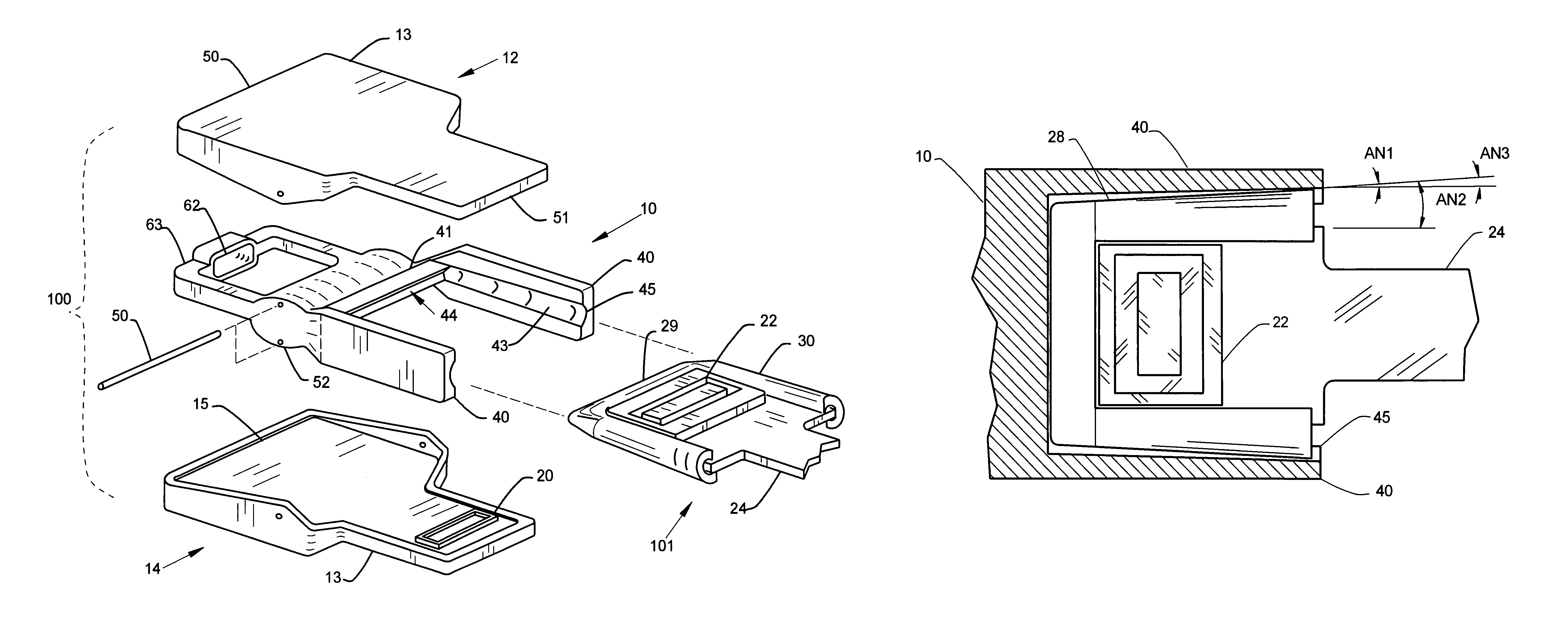
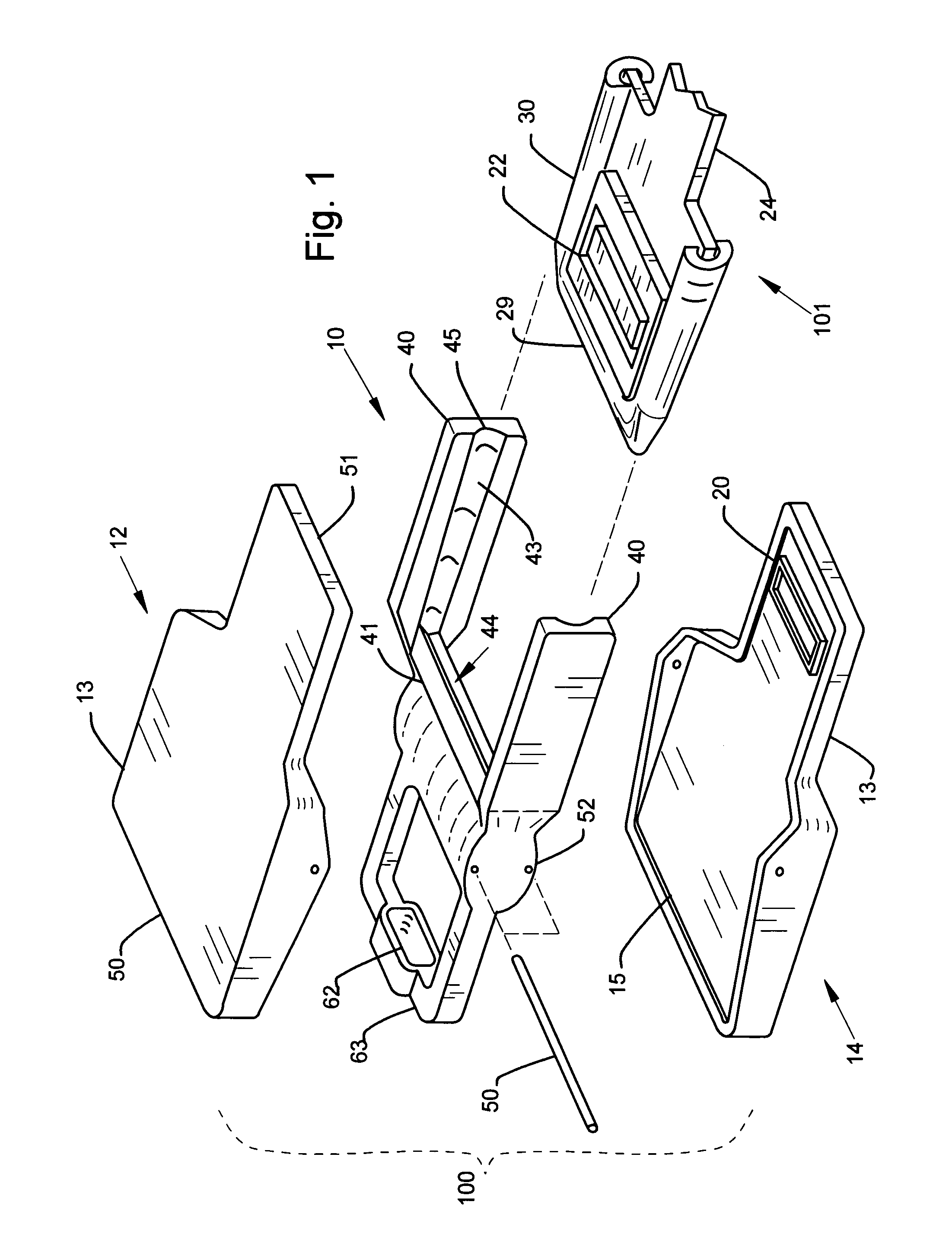
[0019]FIG. 1 is an exploded perspective view of a preferred embodiment of the inventive connector. The immediately following is a general description of this embodiment and its basic components and their relations. The connector includes a female connector assembly element 100 of multiple parts that move relatively, to physically and electrically engage and disengage a male connector element 101. The female element 100 includes a rigid register frame 10 configured to receive and relatively position the male element 101. The female element 100 also includes both an upper and lower frame 12, 14 that are each pivotably connected to opposite top and bottom sides of the register frame 10. Each frame 12, 14 includes an insulating cover 13 and retained circuit board (CB) 15 on which is mounted a female portion 20 of an electrical “snap” connector.

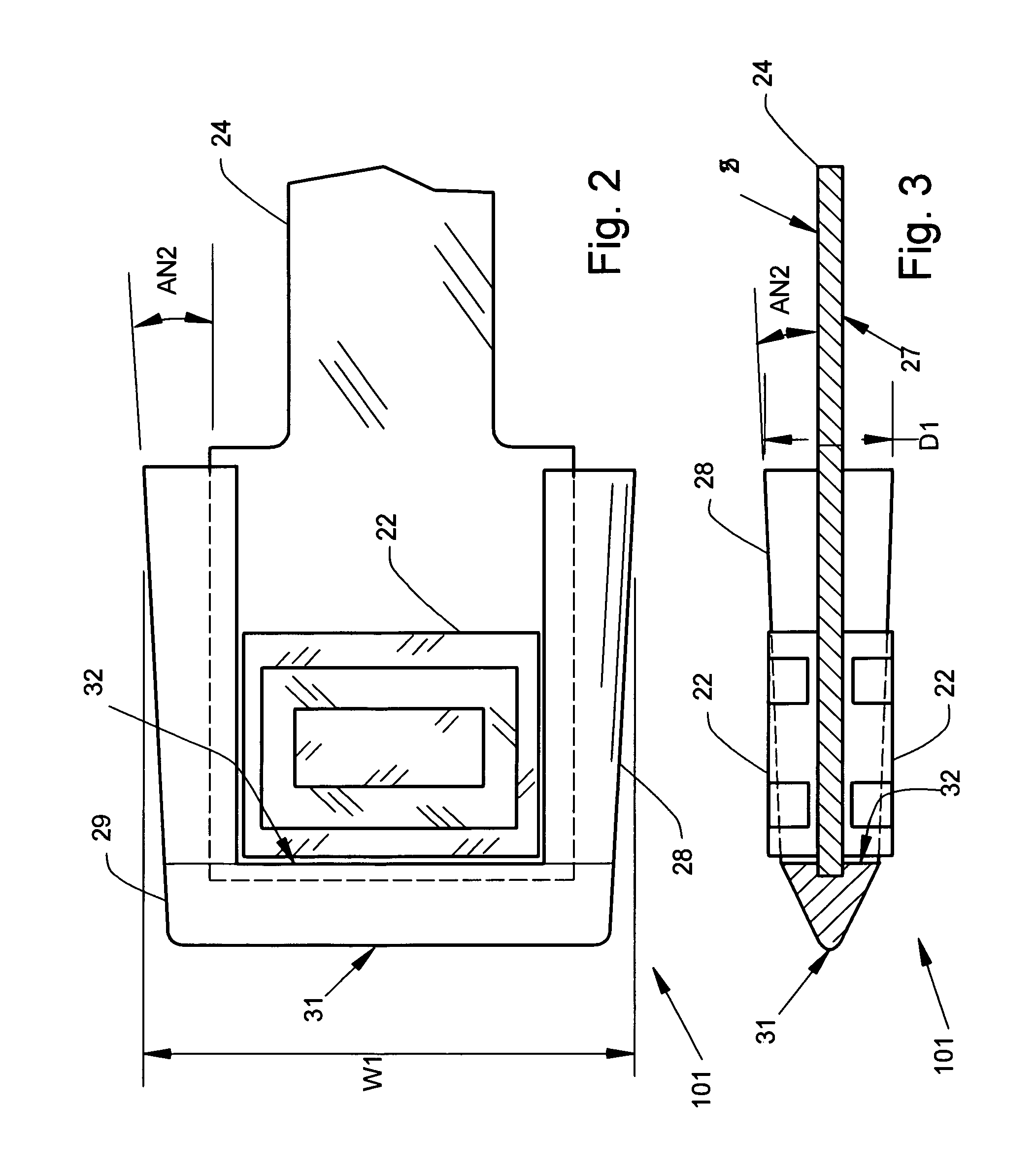
[0020]The male element 101 is formed by an elongated CB 24 and a hood frame 30 that covers one end of the elongated CB 24. A mating, male, portio...


PUM


Abstract

A releaseable multi-channel electrical connector is designed for small size, and ease of use without generating manipulation forces that might be transmitted to an attached living subject. Two pivoting frame members on which electrical snap connectors are mounted are oriented such that the two snap connectors face a male connector element placed between the two frames. The male connector includes mating snap connectors on opposing sides that join with the snap connectors on the frames when the frames are squeezed together. Because two frames are squeezed together with opposing forces to make a connection, no net force is generated or transmitted to the male element nor to attached subject bodies. The use of two snap connectors on opposing sides on a single male element increases the conductor density over prior devices.

Description

RELATED APPLICATIONS[0001]None.BACKGROUND OF THE INVENTION[0002]The present invention pertains to multiple conductor electrical connectors, particularly electrical connectors providing both high density and high number of conductors. Most particularly, the invention is a three-piece pivoting frame which is operated to retain and manipulate two sets of conductors to connect with both sides of an inserted two-sided connector body. The novel combination of the frame and two-sided geometry provides novel benefits including unconventionally high density and zero net force connection and disconnect operations.[0003]In many applications such as clinical neurological testing of animals, there is often a need for electrical devices with large numbers of distinct electrical circuits and hence equally large numbers of electrical conductors. For many reasons, it is desirable for these conductors to be very small and, in the aggregate, to take up very little space. Particularly in medical resear...

Claims


Application Information

Patent Timeline
IPC IPC(8): H01R11/22
CPCH01R13/627H01R13/631Y10S439/909
Inventor TUCKER, TIMOTHY J.
Owner ORACLE INT CORP
Why Eureka
Try Eureka