LED connector assembly with heat sink

a technology of led connectors and heat sinks, which is applied in the direction of semiconductor devices for light sources, coupling device connections, lighting and heating apparatus, etc., can solve the problems of shortening the useful life of leds, damage to the light fixture housing, and thermal and interconnection problems, so as to achieve the effect of dissipating heat from the printed circuit board, high intensity and high efficiency

Active Publication Date: 2009-06-02
TYCO ELECTRONICS LOGISTICS AG (CH)
View PDF25 Cites 120 Cited by
  • Summary
  • Abstract
  • Description
  • Claims
  • Application Information

AI Technical Summary

Problems solved by technology

This frequently results in thermal and interconnection problems with the LED assembly packaging.
The heat accumulation may damage the LEDs themselves, resulting in shorter useful life of the LEDs, or cause damage to the light fixture housings such as warping and discoloration.

Method used


Image

  • LED connector assembly with heat sink
  • LED connector assembly with heat sink
  • LED connector assembly with heat sink

Examples


Embodiment Construction

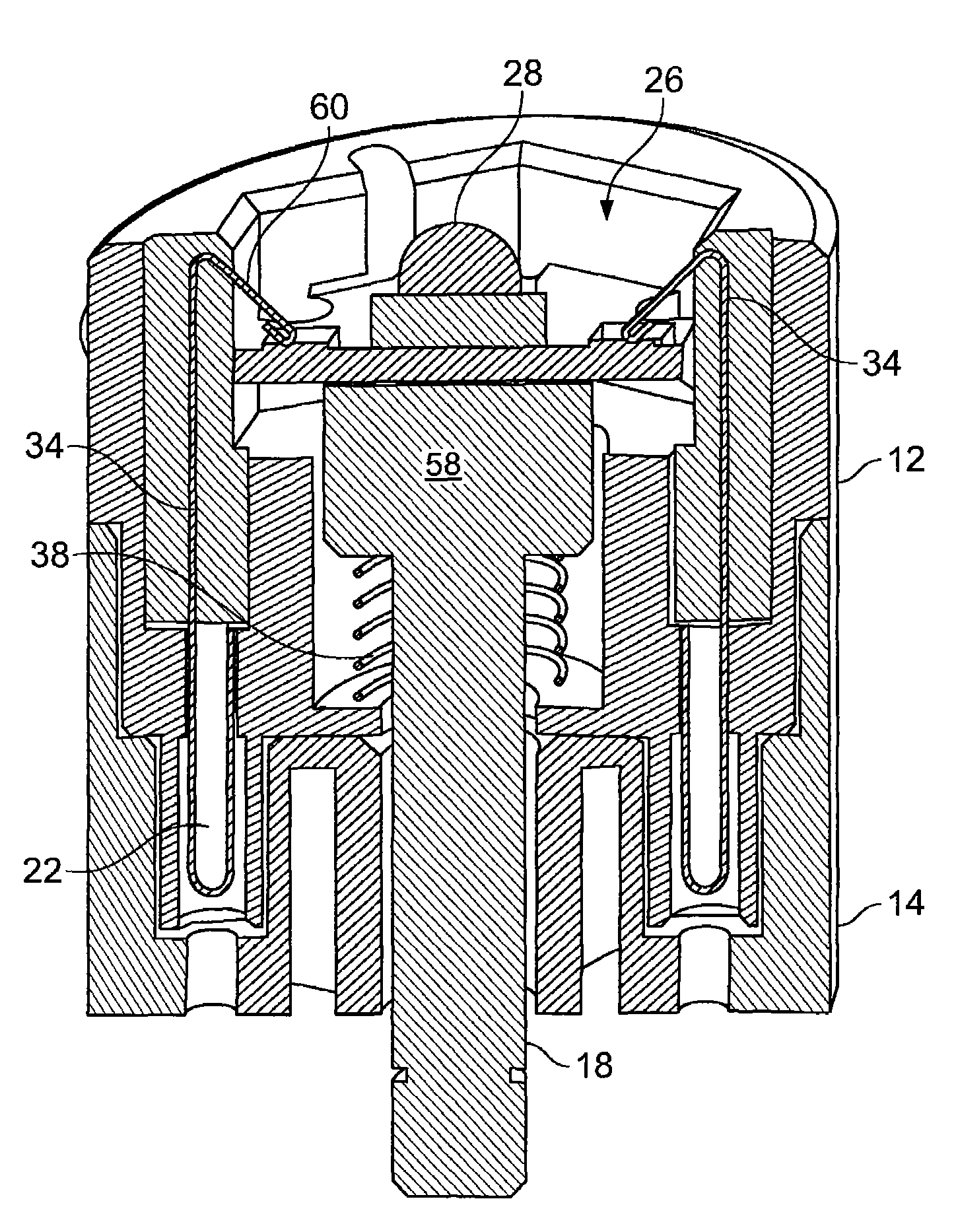
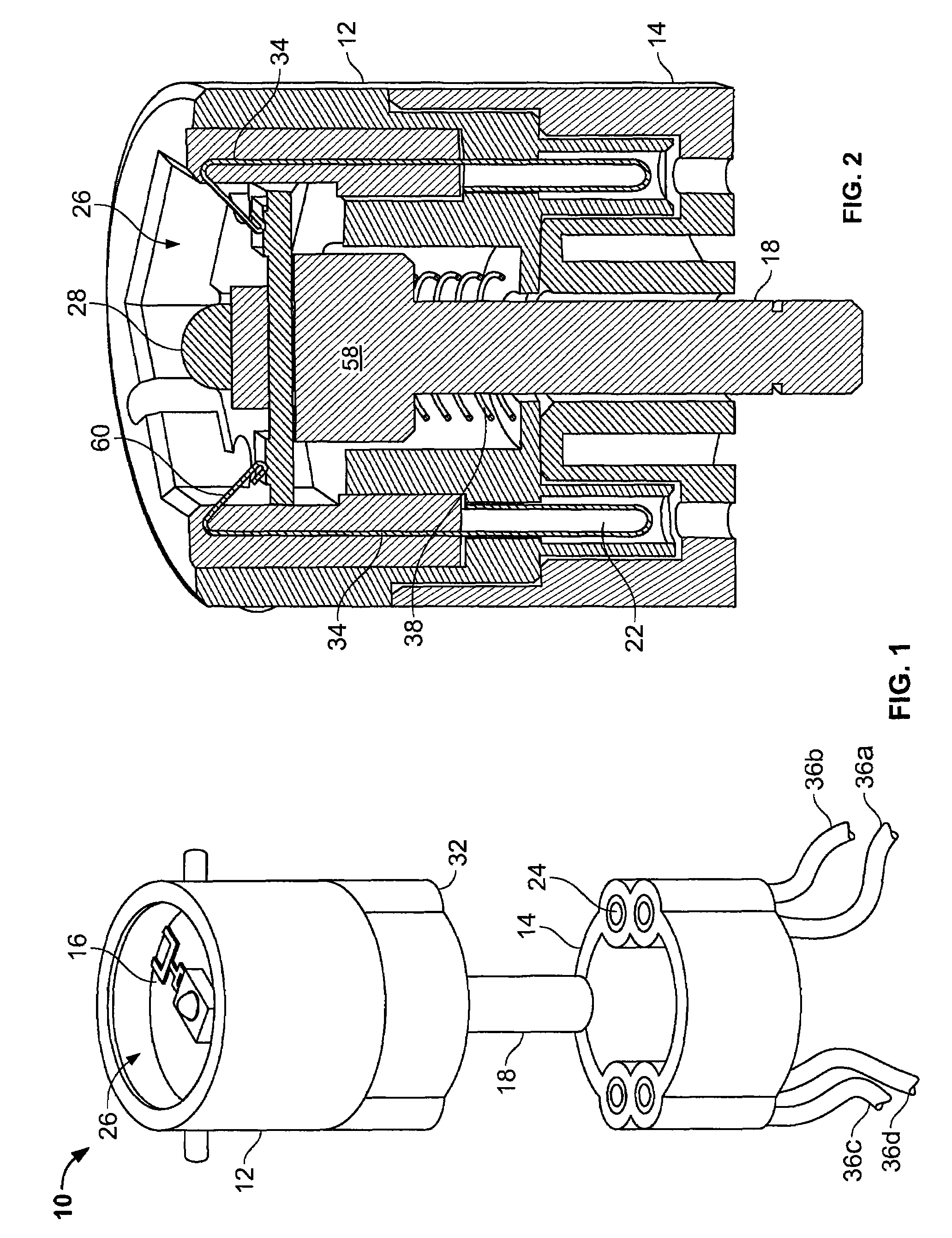
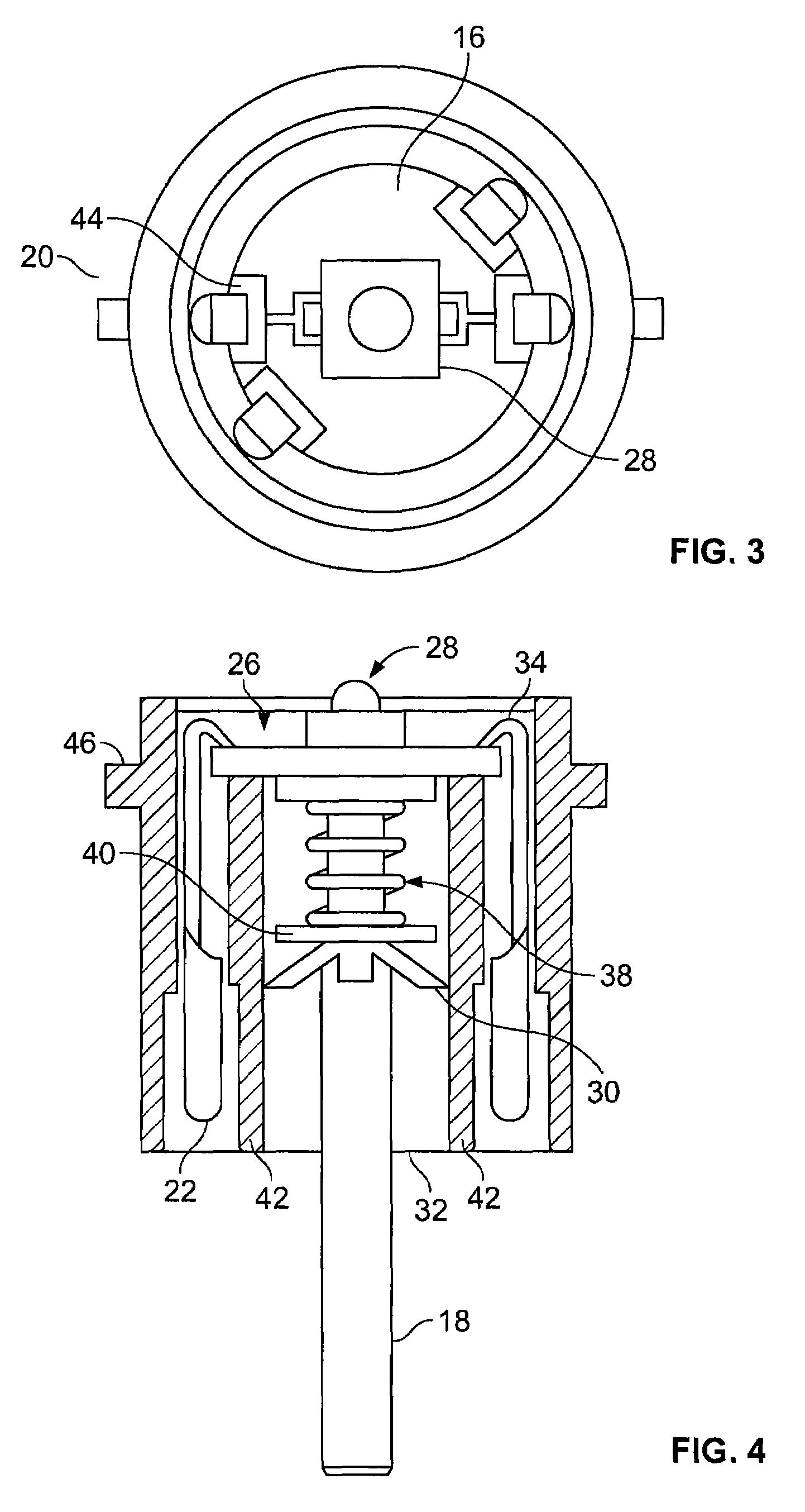
[0020]The present invention is a universal LED connector assembly that accepts a conventional LED printed circuit board (PCB) containing at least one high intensity LED. The PCB can be of conventional construction, or may include thermally conductive cladding such as aluminum. Each LED circuit board represents a component or pixel of a larger image or light source. The LED connector assembly is designed to be independent of the actual LED device that is used. The LED PCBs are for use in various architectural and general-purpose lighting fixtures, signs and video displays, traffic signals and various other applications using high intensity LEDs. The lighting fixture typically provides a housing or structure that supports the LED light source. The structure provides power connections to the LED light source, and provides openings through which the light shines when the light source (or sources) is energized. When used herein, the word lighting fixture is meant to include all general a...


PUM


Abstract

A universal mounting supports high intensity LEDs in a lighting fixture with heat removal and electrical connection facilities. A holder includes a peripheral sidewall defining a cavity for accepting a printed circuit board assembly. A support member supports the printed circuit board assembly along the peripheral sidewall. Electrical contact elements are provided the printed circuit board. A thermal conduction member is in thermal communication with the printed circuit board assembly. The receptacle portion removably engages with the holder portion. A plurality of contact sockets conductively engages the electrical contact elements of the holder portion to interconnect the contact elements to external wires. An aperture in the receptacle portion accepts the thermal conduction member, wherein the thermal conduction member passes through the aperture and into a space for dissipating heat from the printed circuit board.

Description

FIELD OF THE INVENTION[0001]The present invention is directed to electronic components, and more particularly to a universal holder assembly for light emitting diodes (LEDs).BACKGROUND[0002]The use of high intensity LEDs for general-purpose illumination, and in specialty lighting applications such as architectural and video display applications, has increased in recent years. Typically, manufacturers of LED lighting assemblies design assemblies that are customized for the specific LED devices that are used in the illuminated displays. The electrical interconnections and thermal characteristics of the assemblies are often treated as secondary issues, and dealt with separately from the mechanical and esthetic aspects of the lighting fixture. This frequently results in thermal and interconnection problems with the LED assembly packaging. The heat accumulation may damage the LEDs themselves, resulting in shorter useful life of the LEDs, or cause damage to the light fixture housings such...

Claims


Application Information

Patent Timeline
Patent Type & Authority Patents(United States)
IPC IPC(8): F21V29/00F21K99/00
CPCF21V23/06F21V29/004F21V29/773F21Y2101/02F21V19/0005Y10S362/80F21V29/006F21Y2115/10F21V29/51F21V29/83
Inventor WEBER, RONALD MARTINDAILY, CHRISTOPHER GEORGEGINGRICH, III, CHARLES RAYMOND
Owner TYCO ELECTRONICS LOGISTICS AG (CH)
Why Eureka
Try Eureka