Circuit breaker

a circuit breaker and arc extinguishing capability technology, applied in the field of circuit breakers, can solve the problems of poor contact performance between fixed and movable contacts in a closed state, poor contact performance, and reduced contact area, and achieve the effect of reducing improving the arc extinguishing capability of the circuit breaker, and increasing the amount of evaporating gas

Inactive Publication Date: 2009-06-02
FUJI ELECTRIC FA COMPONENTS & SYST CO LTD
View PDF9 Cites 21 Cited by
  • Summary
  • Abstract
  • Description
  • Claims
  • Application Information

AI Technical Summary

Benefits of technology

[0016]A circuit breaker comprising a current interrupting section as described above has the following effects. In a circuit breaker according to the first aspect, which comprises the magnetic plate interposed in a middle region between the two pairs of fixed and movable contacts at both sides and extending along a path of the switching movement of the movable contactor, the magnetic plate performs a function of a magnetic shield inhibiting interference between the magnetic fields of arcs generated between the pairs of the fixed and movable contactors. As a result, the repulsive electromagnetic force F separating the arcs as shown in FIG. 11(b) is eliminated. The beginning points of the arcs are prevented from moving aside on the surface of the contact, and the abnormal dissipation of the contacts due to this movement is suppressed. Therefore, the poor contact performance between the contacts is effectively avoided in the closed state of the contacts.
[0018]An arc extinguishing effect is additionally produced by a narrow gap current limiting effect that is brought about owing to the structure of the second aspect in which the partition walls of organic polymer material are provided sandwiching each pair of the fixed and movable contacts at both sides thereof to function as the narrow gap arc extinguishing plates and create a narrow gap arc extinguishing space between the partition walls. By combining these partition walls with a grid type arc extinguishing device and disposing in a current interrupting section, the arc extinguishing capability of a circuit breaker is greatly improved.
[0019]In the structure according to another aspect of the invention, the partition walls provided outside the pairs of fixed and movable contacts are composed of an organic polymer material that generates a greater amount of evaporating gas due to the heat of arcing and the partition wall provided inside the pairs of fixed and movable contacts is composed of an organic polymer material that generates a smaller amount of evaporating gas. This structure makes it possible that the repulsive electromagnetic force F acting on the arc between the fixed contact and the movable contact (FIG. 11(b)) is cancelled by the bursting gas flow from the outer partition wall towards the narrow gap arc extinguishing space, the gas flow from the outer partition walls being stronger owing to the difference in the amount of evaporating gas from the outer and inner partition walls. As a result, the arc is pushed back to the central region of the contact surface, so that the abnormal dissipation of the contact is effectively suppressed.
[0020]In the structure according to yet another aspect of the invention, the partition walls provided outside the pairs of fixed and movable contacts are thicker than the partition wall(s) provided inside the pairs of fixed and movable contacts. This structure allows the outer partition walls that evaporate larger amount of gas to prevent from early dissipation and loss of strength for an arc extinguishing plate. It also allows the partition walls to keep the narrow gap current limiting effect stable for a long time.
[0022]The synergy effect allows the pushing back force of the gas to the arc and the repulsive electromagnetic force to separate the arcs each other to be canceled each other. Therefore, the abnormal dissipation (unbalanced dissipation) of the contacts caused by outward shift of the beginning point of the arc, is more effectively suppressed.

Problems solved by technology

The current interrupting section of double-break type as described above, however, has a problem in that abnormal dissipation of the fixed and movable contacts occurs with repeated current interruption as described below, causing poor contact performance between the fixed and movable contacts in a closed state.
This unbalanced dissipation causes poor contact performance (decrease of contact area) between the fixed and movable contacts in the closed state of the contactor mechanism, which in turn leads to troubles such as extraordinary heating and adhesion of the contacts in the current flowing condition.

Method used


Image

  • Circuit breaker
  • Circuit breaker
  • Circuit breaker

Examples


example 1

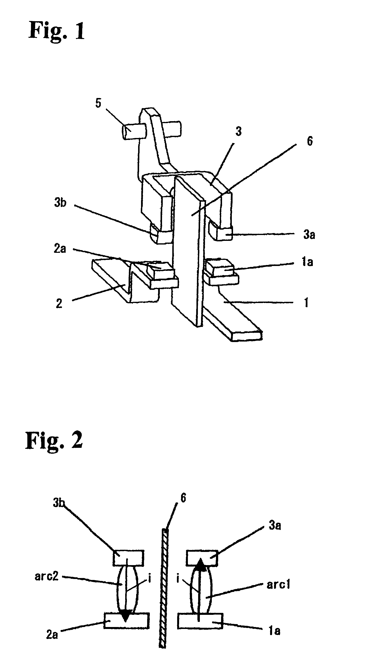
[0035]Now, description will be first made on the structure and function of the invention referring to FIG. 1 and FIG. 2. The contact mechanism of the example shown in these figures is basically similar to the conventional structure shown in FIG. 9. However, a magnetic plate 6 extending vertically is newly provided as shown in FIGS. 1 and 2. The magnetic plate 6 is interposed in a middle region between the fixed contacts 1a and 2a of the first and the second contactors 1 and 2 at both sides and extending along a path of switching movement of the movable contactor 3. A sufficient distance is secured from the magnetic plate 6 to the fixed contactors 1, 2 and the movable contactor 3 so as to inhibit contact between the magnetic plate and the arc generated in the event of current interruption, thereby avoiding short circuit between the fixed contactors 1 and 2 through a current path of the magnetic plate 6.

[0036]In this structure as shown in FIG. 2, the magnetic plate 6 functions as a ma...

example 2

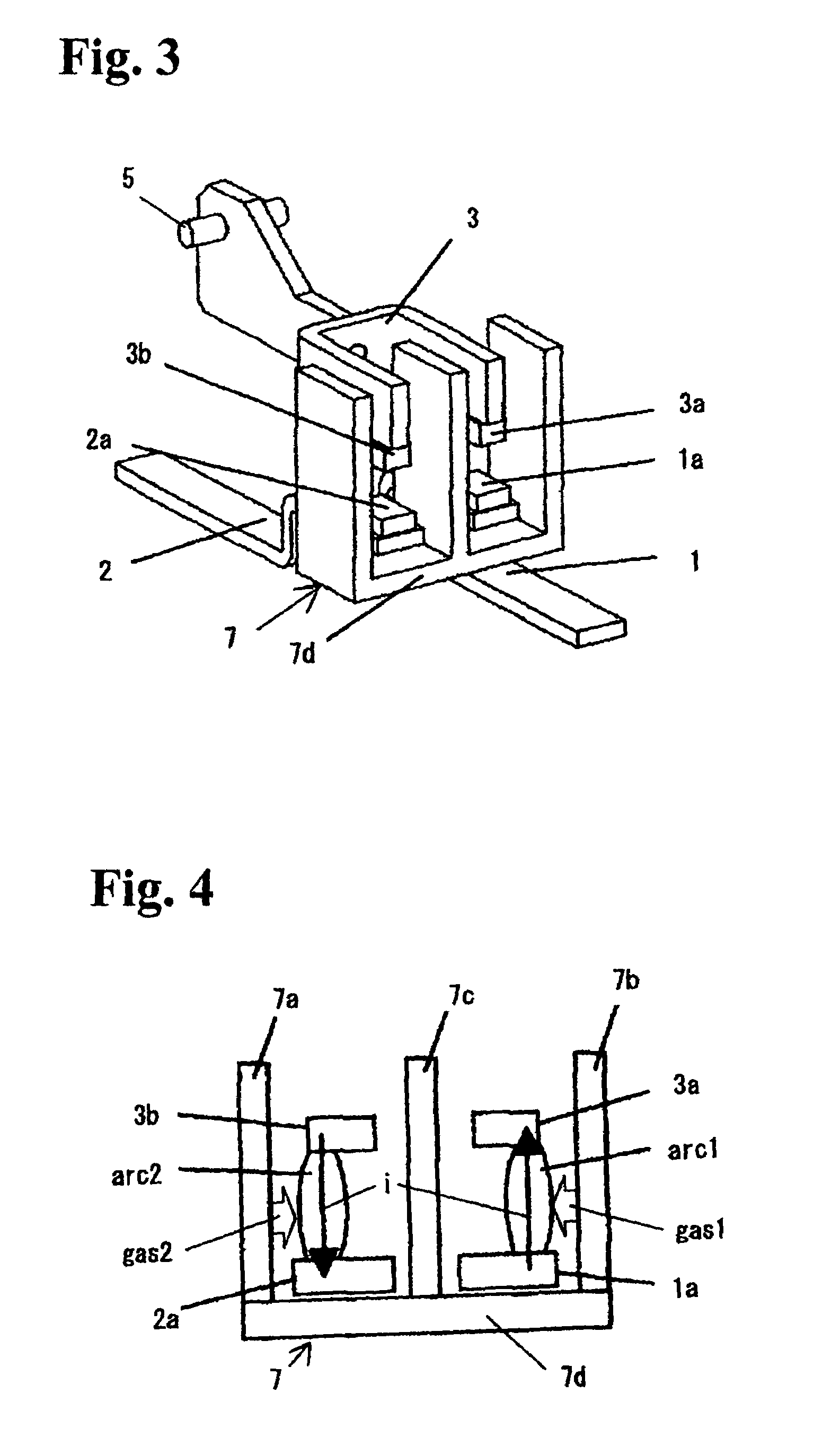
[0038]Next, description will be made on the structure and function of the invention referring to FIG. 3 and FIG. 4. In this example, a narrow gap partition wall assembly 7 is provided by molding a matrix resin of an organic polymer material, the assembly comprising three sheets of partition walls 7a, 7b, 7c and a bottom wall 7d in a configuration of letter “E”. The three sheets of the partition walls are arranged sandwiching the first and second fixed contactors 1, 2 and the U-shaped arm of the bridge type movable contactor 3 along the switching path of the movable contactor 3, forming narrow gap arc extinguishing spaces for the pairs of fixed and movable contacts between the partition walls 7a and 7c, and between the partition walls 7b and 7c.

[0039]When the arc 1 developed between the fixed contact 1a and the movable contact 3a, and the arc 2 developed between the fixed contact 2a and the movable contact 3b in the event of current interruption move away in the opposite directions ...

example 3

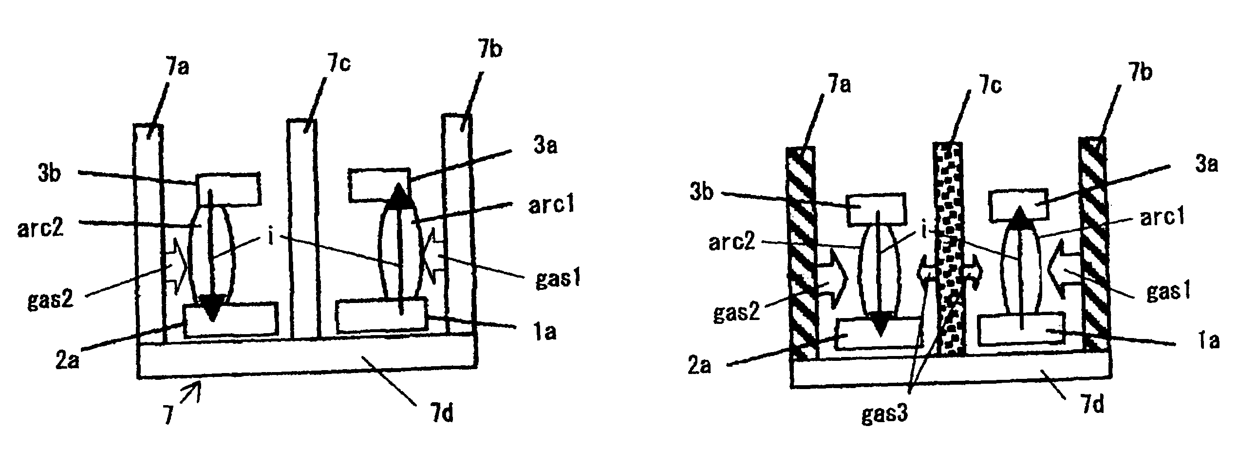
[0042]FIGS. 5(a) and 5(b) show Example 3 that is further improved from Example 2 of the invention. Among the partition walls 7a, 7b, 7c composing the narrow gap partition wall assembly 7 and arranged at both sides and at a center in this Example 3, material of the partition walls 7a and 7b arranged at the both sides is an organic polymer material that is readily decomposed by the heat of arc and evaporates a large amount of gases, while the material of the partition wall 7c arranged at the center is an organic polymer material that evaporates a smaller amount of gases. These materials are used in the partition walls to form narrow gap arc extinguishing spaces between the partition walls. The organic polymer material evaporating a large amount of gases can be selected from polyacetal, poly(methyl methacrylate), and the like; and the organic polymer material evaporating a small amount of gases can be selected from polyamide, polyethylene, poly(fluoroethylene), and the like.

[0043]When ...


PUM


Abstract

A circuit breaker for a double-break mechanism includes a current interrupting section having a contact mechanism. The contact mechanism includes first and second fixed contactors arranged in parallel and having fixed contacts, and a bridging movable contactor having an arm with movable contacts opposing the fixed contacts. A magnetic plate may be interposed in a middle region between two pairs of the fixed and movable contacts extending along a path of switching movement of the movable contactor. Partition walls formed of organic polymer material may be provided to stand along the path of the movable contactor. The partition walls sandwich each pair of the fixed contact and the movable contact to form a narrow gap arc extinguishing space between the partition walls.

Description

BACKGROUND OF THE INVENTION AND RELATED ART STATEMENT[0001]The present invention relates to circuit breakers including molded case circuit breakers and earth leakage breakers, in particular to structures of current interrupting sections in the circuit breakers.[0002]This type of circuit breakers as mentioned above is a double-break type circuit breaker that comprises first and second fixed contactors of a current interrupting section in parallel arrangement, a bridge type rotatably movable contactor that holds movable contacts on the ends of a U-shaped arm, opposing fixed contacts attached on the ends of the fixed contactors, and a grid type arc extinguishing device which is disposed opposing and in front of the movable contactor (for example Japanese Patent Publication (Kokai) No. 11-273536).[0003]FIG. 8 and FIG. 9 show a conventional structure of the double-break type circuit breaker and its current interrupting section. Referring to FIG. 8, the circuit breaker comprises a main bo...

Claims


Application Information

Patent Timeline
Patent Type & Authority Patents(United States)
IPC IPC(8): H01H9/30
CPCH01H9/302H01H9/34H01H9/446H01H73/18
Inventor NAKANO, MASAAKISUGIYAMA, SYUICHIISOZAKI, MASARU
Owner FUJI ELECTRIC FA COMPONENTS & SYST CO LTD
Why Eureka
Try Eureka