Resistance plate and liquid level detection apparatus provided with said resistance plate

a technology of resistance plate and resistance plate, which is applied in the direction of liquid/fluent solid measurement, machines/engines, instruments, etc., can solve the problems of deterioration and corrosion of the proportion 111/b>, and achieve the effect of reducing the influence of electrolysis and producing at a relatively low cos

Inactive Publication Date: 2009-06-02
YAZAKI CORP
View PDF6 Cites 15 Cited by
  • Summary
  • Abstract
  • Description
  • Claims
  • Application Information

AI Technical Summary

Benefits of technology

[0011]This invention has been made in view of the above circumstances, and an object of the invention is to provide a resistance plate which can alleviate the influence of electrolysis occurring as when the resistance plate is immersed in an electrolyte, and besides can be produced at a relatively low cost, and also to provide a liquid level detection apparatus provided with this resistance plate.

Problems solved by technology

Therefore, this portion 111 is liable to be most affected by electrolysis occurring as when the resistance plate is immersed in the fuel, and there is a high possibility that this portion 111 may be deteriorated and corroded.

Method used


Image

  • Resistance plate and liquid level detection apparatus provided with said resistance plate
  • Resistance plate and liquid level detection apparatus provided with said resistance plate
  • Resistance plate and liquid level detection apparatus provided with said resistance plate

Examples


Embodiment Construction

” with reference to the accompanying drawings.

BRIEF DESCRIPTION OF THE DRAWINGS

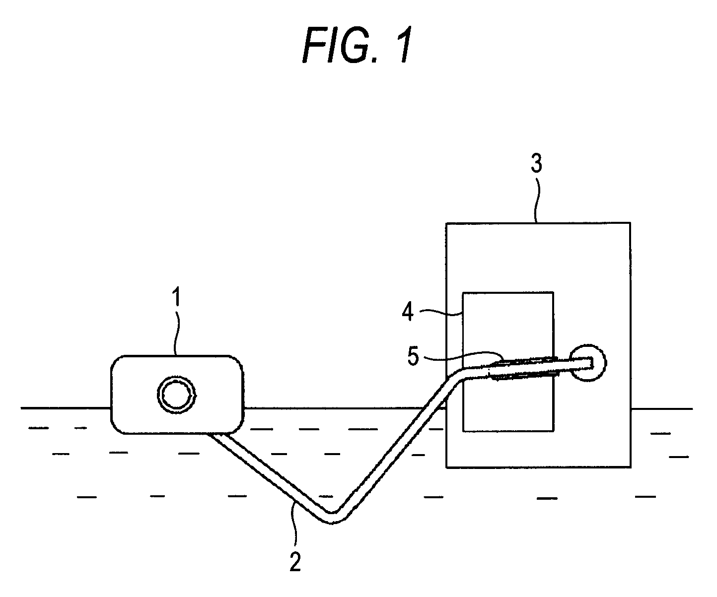
[0045]FIG. 1 shows one preferred embodiment of the present invention, and is a view broadly showing the construction of a liquid level detection apparatus.

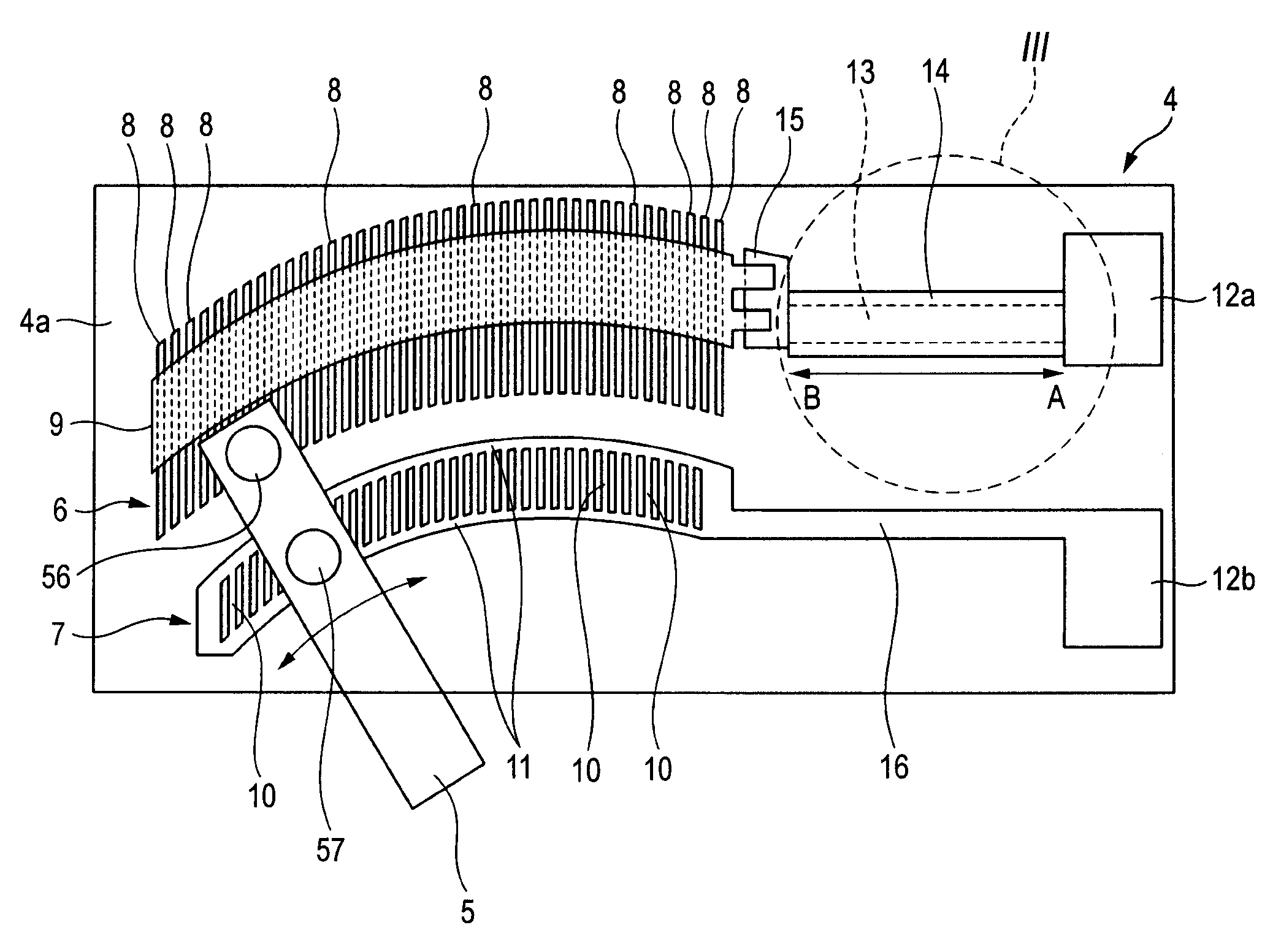
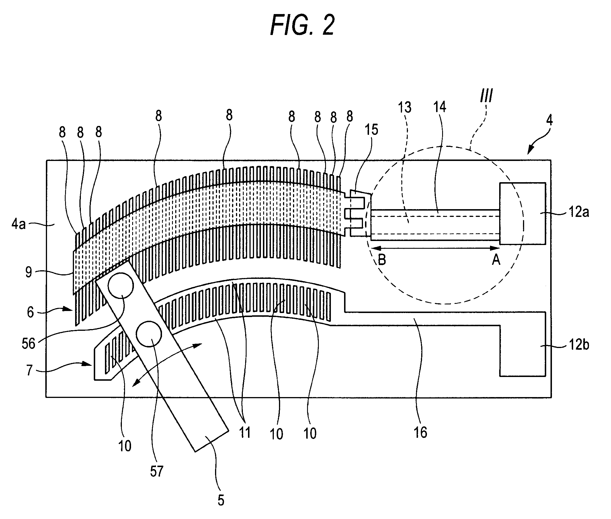
[0046]FIG. 2 shows the preferred embodiment of the invention, and is a plan view explanatory of a resistance plate used in the liquid level detection apparatus of FIG. 1.

[0047]FIG. 3 is an enlarged view of a portion of FIG. 2 encircled by a broken line III.

[0048]FIG. 4 is a cross-sectional view taken along the line IV-IV of FIG. 3.

[0049]FIG. 5 is an equivalent circuit diagram showing in a simplified manner an electric circuit formed on an insulating layer of the resistance plate of FIG. 2 as well as one example of a detector electrically connected to the electric circuit.

[0050]FIG. 6 is a view explanatory of a resistance plate used in a conventional liquid level detection apparatus.

DETAILED DESCRIPTION OF THE PREFERRED EMBODIMENTS

[0051]A preferred embod...


PUM


Abstract

In a resistance plate, a first slide portion includes a plurality of first conductive segments arranged at intervals generally in a direction of sliding movement of a sliding arm, the adjacent first conductive segments being connected together via a resistor. A first conducting path 13 extends between the first slide portion and a first end land to electrically connect them together, the first end land being provided for detecting a quantity of electricity appearing according to the positions of the first conductive segment and a second conductive segment which are held in contact with the sliding arm. A protector is formed on the first conducting path to cover this first conducting path. The protector and the resistor are made of the same material.

Description

BACKGROUND OF THE INVENTION[0001]1. Field of the Invention[0002]This invention relates to a liquid level detection apparatus suited for detecting a liquid level (or height) within a fuel tank of an automobile, and more particularly to an improved resistance plate used in a liquid level detection apparatus in which a float arm connected at its distal end to a float is pivotally moved in accordance with displacement of the float floating on the liquid surface, and a sliding arm slides over the resistance plate in accordance with the pivotal movement of the float arm.[0003]2. Related Art[0004]One conventional liquid level detection apparatus disclosed in Japanese Patent No. 3,833,551 Specification will be described with reference to FIG. 6. As shown in FIG. 6, the liquid level detection apparatus 100 includes a resistance plate 101, and a sliding arm 102 for sliding over this resistance plate 101 in accordance with a pivotal movement of a float arm (not shown). A first slide portion 10...

Claims


Application Information

Patent Timeline
Patent Type & Authority Patents(United States)
IPC IPC(8): H01C1/14
CPCG01F23/36
Inventor KAWAGUCHI, YASUNORITANAKA, KENICHIOIKE, TOSHIO
Owner YAZAKI CORP
Why Eureka
Try Eureka