
Storage system chassis and components

Active Publication Date: 2009-06-02
NETWORK APPLIANCE INC
View PDF28 Cites 19 Cited by
  • Summary
  • Abstract
  • Description
  • Claims
  • Application Information

AI Technical Summary

Benefits of technology

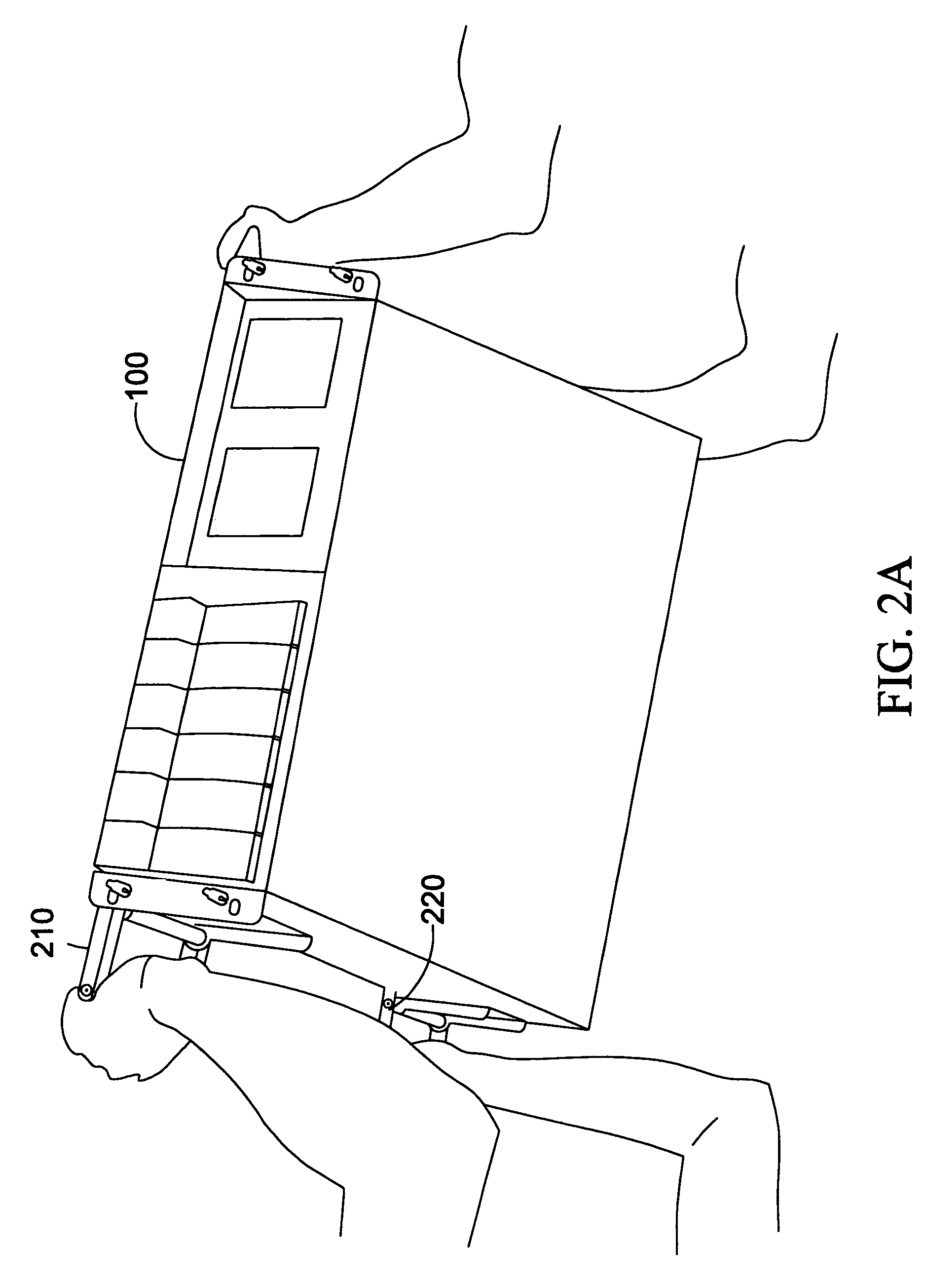
[0006]Accordingly, the present invention is directed to an apparatus including a computing appliance chassis assembly which may support an integration of a plurality of removable modules, including fan modules, power supplies, and a controller module. The computing appliance chassis assembly may also include detachable handles. The detachable handles may allow transport of the computing appliance chassis assembly and may be removed without tools when the computing appliance chassis assembly is mounted within a storage rack.
[0007]The present invention is further directed to a controller chassis for housing a controller module in accordance with an embodiment of the invention. The controller chassis may include rotatable side panels which allow easier access to the components of the controller module. The controller chassis may also include a removable cable tray and a latching paddle to prevent unintended removal of the controller chassis from the computing appliance chassis assembly.
[0008]The present invention is further directed to a fan chassis for housing a fan module in accordance with an embodiment of the invention. The fan chassis may be removably mounted within the computing appliance chassis assembly. The fan chassis may include a handle. The handle of the fan chassis may also include a lightpath for a visible alert. When a fan module fails, a visible alert may light. The lightpath may enhance the ability to detect the visible alert. The fan chassis may also include a detachable visible display module which may provide status and operating information for the computing appliance chassis assembly.

Problems solved by technology

A problem associated with a conventional chassis is the difficulty associated with maintenance of the computing appliance when components are mounted within the chassis in a conventional manner.
Re-installation of a repaired component within the chassis of the computing system, re-installation of the computing system within the storage rack, and coupling of the various communication and power cables may also be similarly burdensome.

Method used


Image

  • Storage system chassis and components
  • Storage system chassis and components
  • Storage system chassis and components

Examples


Embodiment Construction

[0029]Reference will now be made in detail to the presently preferred embodiments of the invention, examples of which are illustrated in the accompanying drawings.

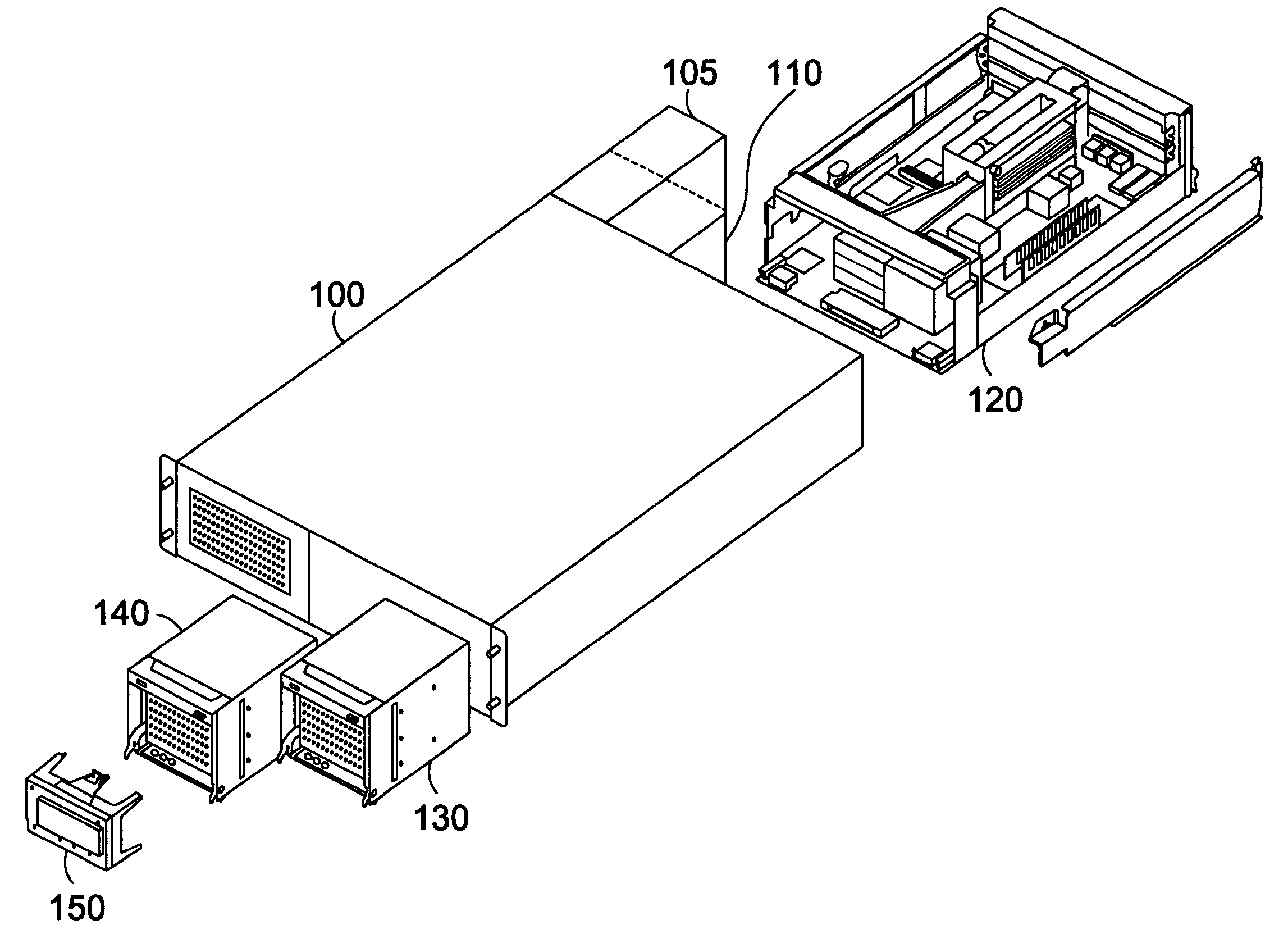
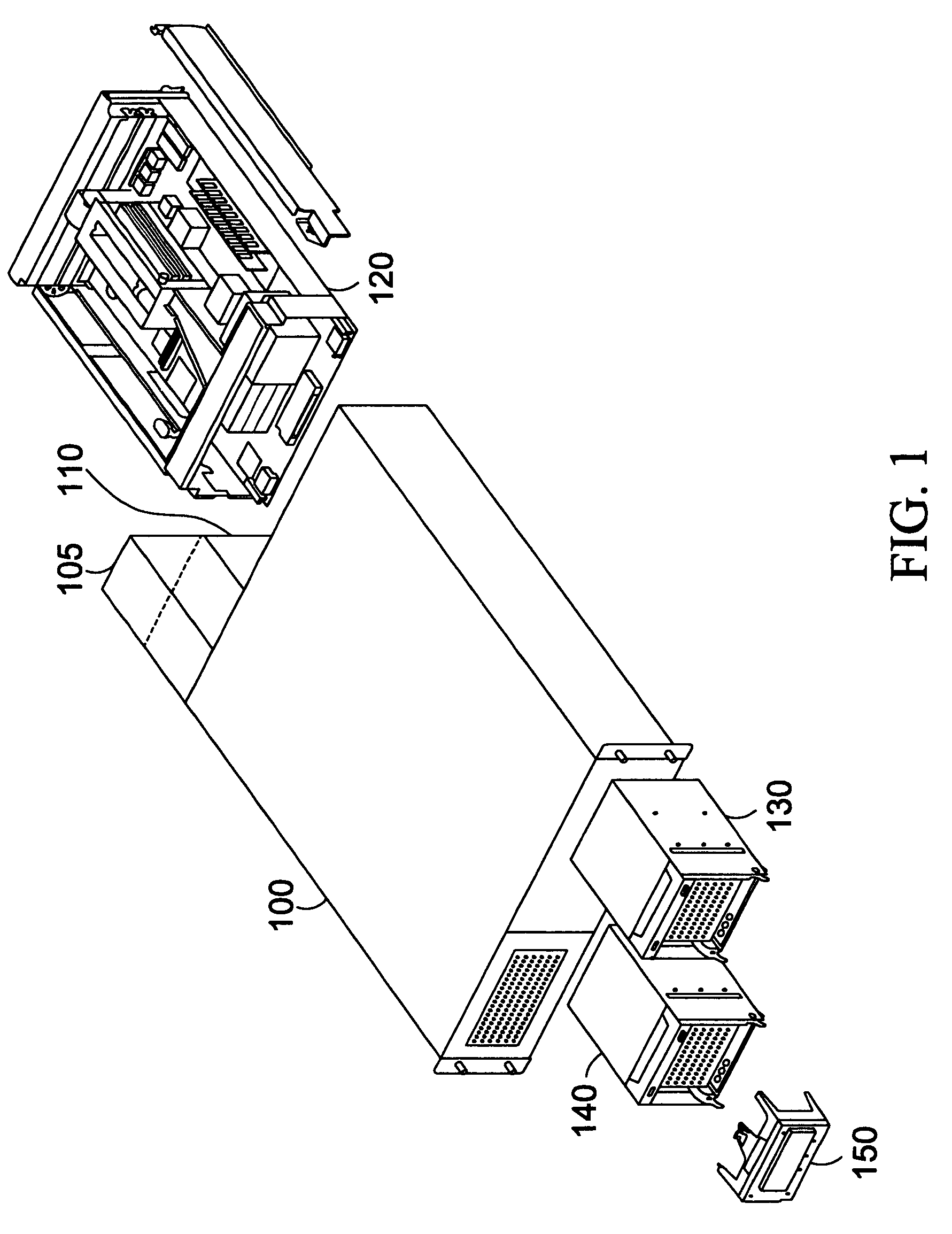
[0030]Referring to FIG. 1, a computing appliance chassis assembly 100 in accordance with an embodiment of the invention is shown. Computing appliance chassis assembly 100 may be suitable for housing a plurality of modularized components, such as power supplies 105, 110, a controller module and fan modules. Controller module may be housed within a controller chassis 120 which is removably mountable within the computing appliance chassis assembly 100. Fan modules may be housed within fan chassis 130, 140 which may also be removably mountable within computing appliance chassis assembly 100. Computing appliance chassis assembly 100 may include two sides, a top and a base section. The two sides, top and base section may be constructed of a rigid metal. The height of each side may be suitable for providing a secure fit for each ...


PUM


Abstract

The present invention is a computing appliance chassis assembly which may support an integration of a plurality of removable modules, including fan modules, power supplies, and a controller module. The computing appliance chassis assembly may also include detachable handles which may allow transport of the computing appliance chassis assembly. A controller chassis may be installed within the computing appliance chassis assembly. A controller chassis assembly may house a controller module and may include rotatable side panels which allow easier access to the components of the controller module. A fan chassis assembly may also be installed within the computing appliance chassis and may house a fan module.

Description

FIELD OF THE INVENTION[0001]The present invention generally relates to the field of computing appliances, and more particularly to a chassis assembly of a computing appliance.BACKGROUND OF THE INVENTION[0002]The efficient and precise storage of electronic data is one of the most important considerations of modern life. Businesses, schools and governments rely upon mass storage in daily operations. Consequently, mass storage systems have been developed to provide persistent and reliable data storage.[0003]A typical storage system may include a computing appliance which may be operatively coupled to mass storage devices according to various communication protocols. A computing appliance may refer to a programmable machine capable of executing a list of instructions. A computing appliance may include a processing unit which executes instructions and memory for storage of data and execution instructions. A mass storage device may refer to devices for retention of data, including floppy ...

Claims


Application Information

Patent Timeline
IPC IPC(8): H05K5/00A47B81/00H05K7/16
CPCG06F1/183H05K7/1411H05K7/20581
Inventor LUI, KWOKHO, DANWILLHEIM, DAVIDBONDI, SALVATORE
Owner NETWORK APPLIANCE INC
Learn More