Loudspeaker

a loudspeaker and harmonic distortion technology, applied in the field of loudspeakers, can solve the problems of difficult to completely suppress difficult to perfectly equalize the upper and lower amplitudes, etc., and achieve the effect of further reducing the harmonic distortion of a loudspeaker

Active Publication Date: 2009-06-02
PANASONIC CORP
View PDF4 Cites 9 Cited by
  • Summary
  • Abstract
  • Description
  • Claims
  • Application Information

AI Technical Summary

Benefits of technology

[0007]With such a configuration, the difference between the compliance by the second edge and the compliance by the first edge can be excluded, and the harmonic distortion of a loudspeaker can be further reduced.

Problems solved by technology

Therefore, it has been difficult to perfectly equalize the upper and lower amplitudes of diaphragm 3, thus making it difficult to completely suppress the harmonic distortion of a loudspeaker.

Method used


Image

  • Loudspeaker
  • Loudspeaker
  • Loudspeaker

Examples


Embodiment Construction

Exemplary Embodiment

[0023]Hereinafter, an exemplary embodiment of the present invention is described with reference to drawings. In the description, the same reference numbers refer to the same configurations described above as a background art.

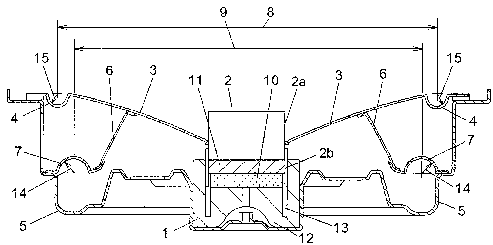
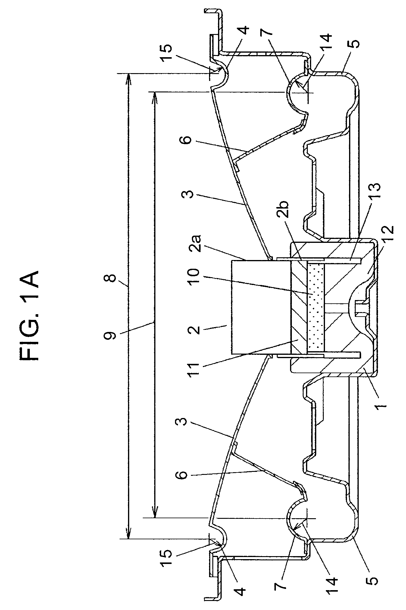
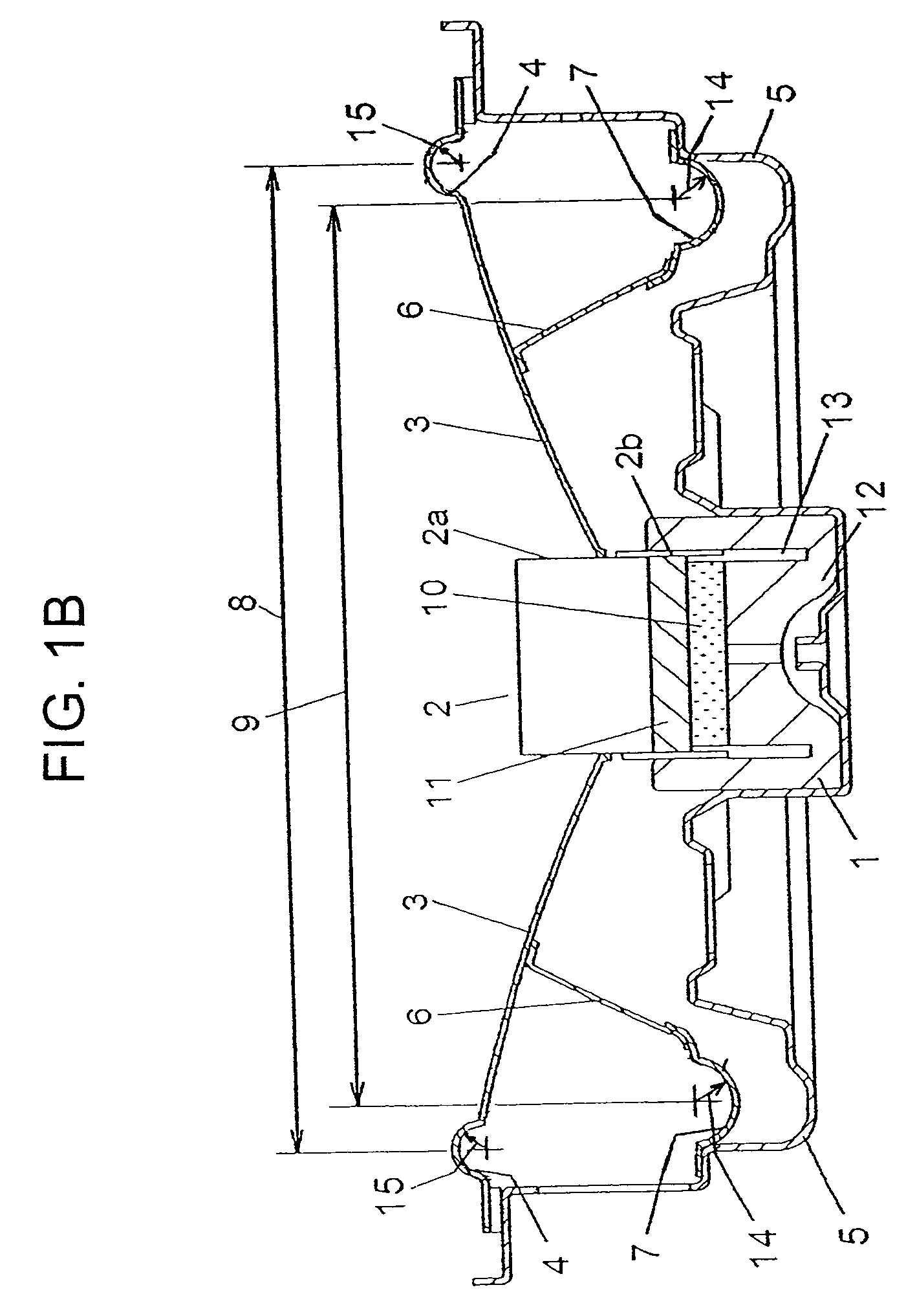
[0024]Fig. 1A is a sectional view showing a loudspeaker in accordance with an exemplary embodiment of the present invention. Magnetic circuit 1 disposed in the middle of the bottom part of frame 5 is constructed by combining and adhesively bonding magnet 10, plate 11 and yoke 12. Magnetic circuit 1 is provided with magnetic gap 13 opening toward the upper side of the loudspeaker. Voice coil unit 2 has a structure including cylindrical main body 2a and coil 2b wound around the outer circumferential part of main body 2a and is disposed slidably with respect to magnetic gap 13, in which the sliding allows the amplitude of diaphragm 3. Diaphragm 3 is coupled to the upper part of voice coil unit 2 at its inner circumferential end part and to the o...


PUM


Abstract

A loudspeaker has a configuration in which edge diameter in the cross section of second edge coupled to suspension holder is set to be larger than edge diameter in the cross section of first edge coupled to diaphragm. With such a configuration, a loudspeaker with reduced harmonic distortion is provided.

Description

[0001]This application is a U.S. national phase application of PCT international applicaton PCT / JP / 2005 / 002751.TECHNICAL FIELD[0002]The present invention relates to a loudspeaker.BACKGROUND ART[0003]FIG. 5 is a sectional view showing a conventional loudspeaker. As shown in FIG. 5, a conventional loudspeaker has a structure in which voice coil unit 2 that is slidably disposed on magnetic circuit 1 is coupled to the inner circumferential end of diaphragm 3, the outer circumferential end of diaphragm 3 is coupled to frame 5 via first edge 4, and furthermore, the rear surface of diaphragm 3 is coupled to frame 5 via suspension holder 6 and second edge 7. In this structure, since first edge 4 and second edge 7 are symmetric to each other, harmonic distortion of a loudspeaker is reduced and power linearity is improved. Information of prior art document relating to the invention of this application is disclosed in, for example, Japanese Patent Unexamined Publication No. 2004-7335.[0004]In ...

Claims


Application Information

Patent Timeline
Patent Type & Authority Patents(United States)
IPC IPC(8): H04R1/00H04R7/20H04R9/06H04R9/02
CPCH04R7/18H04R7/26H04R9/043H04R2307/201H04R2307/207H04R2499/13
Inventor FUNAHASHI, OSAMU
Owner PANASONIC CORP
Why Eureka
Try Eureka