
Multimedia terminal

a multi-media terminal and terminal technology, applied in the field of multi-media terminals, can solve the problems of inability to universally usable mount locations for retrofittable remote controls, limited display units, and general relatively small display units, and achieve the effect of universal usability and preventing th

Inactive Publication Date: 2009-06-02
ROBERT BOSCH GMBH
View PDF12 Cites 1 Cited by
  • Summary
  • Abstract
  • Description
  • Claims
  • Application Information

AI Technical Summary

Benefits of technology

The present invention provides an improved multimedia terminal with a removable operator unit that is universally usable, prevents theft, and adapted to different user groups. The operator unit has a remote transmission unit for wireless transmission of control signals to the multimedia terminal, which improves space utilization for the display unit when the remote control is removed. The operator unit can be easily clamped onto the multimedia terminal and contacted electrically at the same time without requiring further space-using devices. The display unit is designed for indicating control instructions which are assigned to immediately adjacent operating elements of the operator unit, forming soft keys. The soft key system is deactivated when the operator unit is removed, and the assignment of the control functions to the operating elements can be changed. A coupling unit separate from the multimedia terminal can be provided for mechanically and electrically accommodating the operator unit. The remote transmission unit has a wireless radio interface or infrared interface.

Problems solved by technology

Due to the different installation situations and space conditions of different vehicle types, there is disadvantageously no universally usable mounting location for retrofittable remote controls.
Furthermore, there is the problem in conventional multimedia terminals that the size of the available display unit is extremely limited due to the number of operating elements of the operator unit necessary for operation.
This results in the fact that the display unit is generally relatively small and thus poorly readable and only able to display a small number of pieces of information.

Method used


Image

  • Multimedia terminal
  • Multimedia terminal

Examples


Embodiment Construction

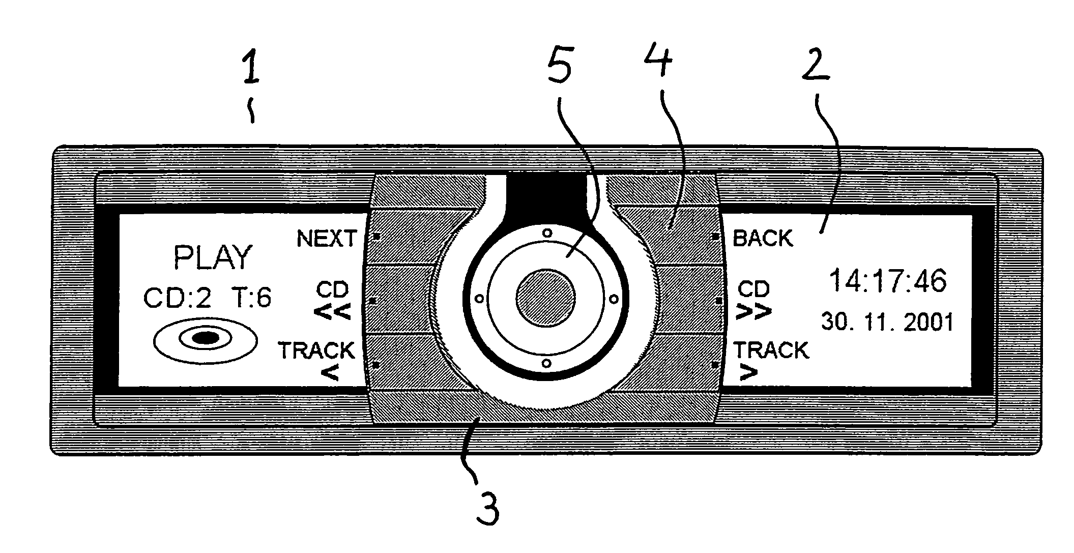
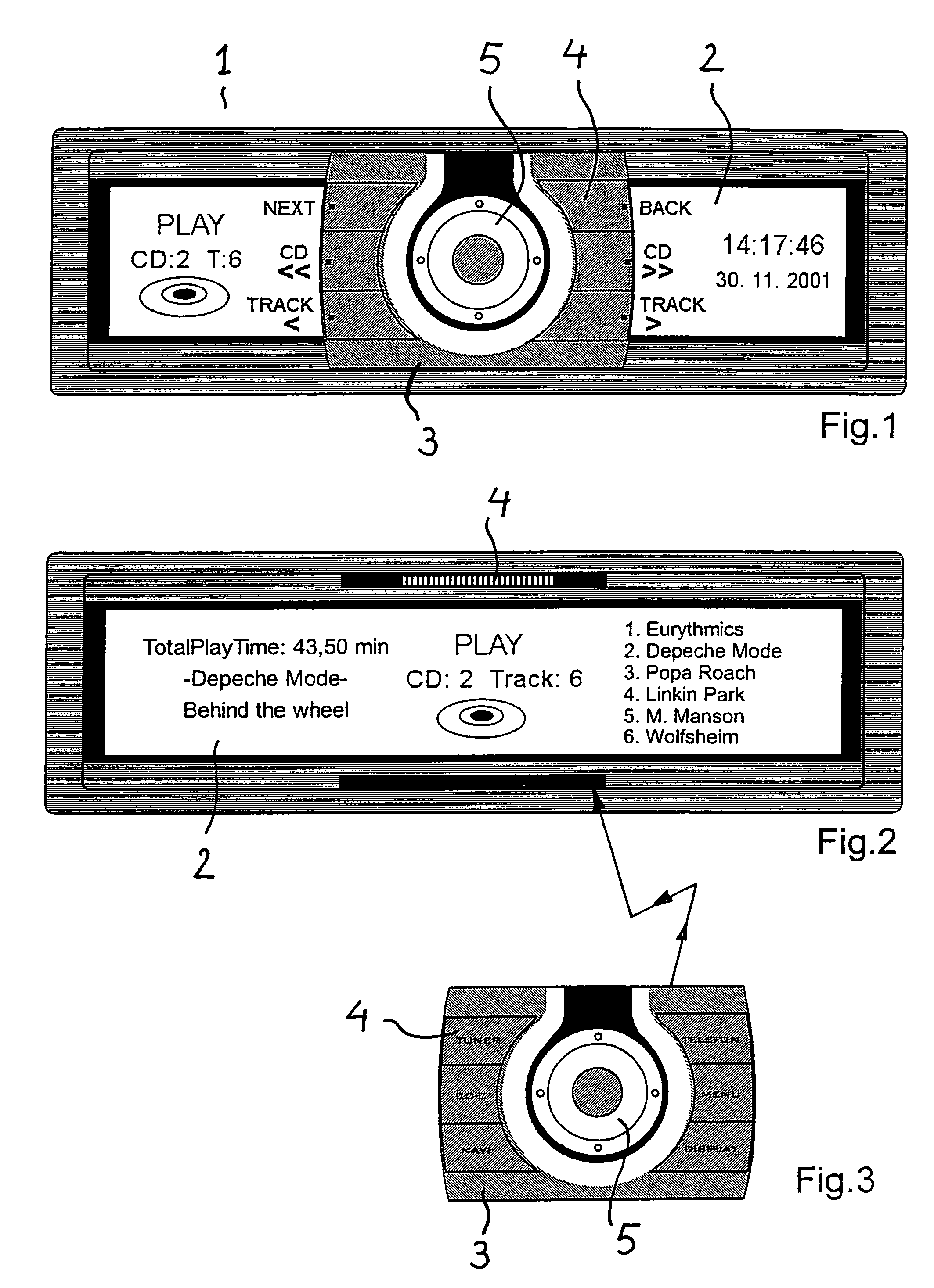
[0019]FIG. 1 shows a front view of a car radio 1 whose operating front is essentially formed by a display unit 2. An operator unit 3 as a removable remote control is mountable on display unit 2, and the operator unit is detachably mechanically and electrically connected to car radio 1 via contacts 4 shown in FIG. 2. Operator unit 3 has multiple operating elements 4 in the form of keys and preferably a rotary knob 5 which may be used, for example, for running through a menu structure and which may also be used for regulating the volume, etc.

[0020]In the state shown in FIG. 1 in which operator unit 3 is mounted on the operating front of car radio 1, display unit 2 is switched to the reduced display mode. The indicated information is reduced to a degree necessary for operation by an unpracticed user. Directly alongside operating elements 4, display unit 2 additionally indicates control instructions such as “NEXT,”“CD >,” and “TRACK>” for fast-forward and rewind during playback of a com...


PUM


Abstract

In the described multimedia terminal, a car radio in particular, including a display unit and an operator unit, the operator unit being removable from the multimedia terminal and having operating elements for controlling the multimedia terminal, the operator unit is a remote transmission unit for wireless transmission of control signals to the multimedia terminal, the control signals being able to be generated by using the operating elements.

Description

FIELD OF THE INVENTION[0001]The present invention relates to a multimedia terminal, a car radio in particular, including a display unit and an operator unit, the operator unit being removable from the multimedia terminal and having operating elements for controlling the multimedia terminal.BACKGROUND INFORMATION[0002]Car radios are widely known in which an operator unit having operating elements essential for controlling the car radio, such as station keys, is removable from the front of the car radio. The removable operator unit may be quickly and easily inserted and removed and theft of the car radio, which is inoperable without the operator unit, may be prevented in this way.[0003]Moreover, remote controls for controlling diverse functions which are separate from the multimedia terminal are widely known. The remote controls for controlling car radios may be installed in a vehicle's steering wheel, or on a separate swan neck, or they may be installed in the center console area or ...

Claims


Application Information

Patent Timeline
Patent Type & Authority Patents(United States)
IPC IPC(8): H04B1/08B60R11/00B60R11/02
CPCB60R11/0264H04B1/082B60K37/06B60R2011/008B60K2350/104B60K2350/102B60K2350/1024B60K35/10B60K2360/126B60K2360/143B60K2360/145
Inventor ZUEHLSDORFF, SVEN
Owner ROBERT BOSCH GMBH
Learn More