Threshold setting for a radar level transmitter

a level transmitter and threshold setting technology, applied in the field of threshold level calculation, can solve problems such as detection errors and level measurement errors

Inactive Publication Date: 2009-06-02
ROSEMOUNT INC
View PDF49 Cites 28 Cited by
  • Summary
  • Abstract
  • Description
  • Claims
  • Application Information

AI Technical Summary

Problems solved by technology

In addition to being time-consuming and requiring a trained operator, this method can lead to inaccurate threshold value settings, which can result in detection errors and erroneous level measurement.

Method used


Image

  • Threshold setting for a radar level transmitter
  • Threshold setting for a radar level transmitter
  • Threshold setting for a radar level transmitter

Examples


Embodiment Construction

[0013]The present invention relates to radar level transmitters that can be used to determine the level of materials, such as liquids and solids, contained in a tank, pipe, vessel or other type of container. The present invention automatically determines threshold values which are used by radar level transmitters to locate the levels of the materials.

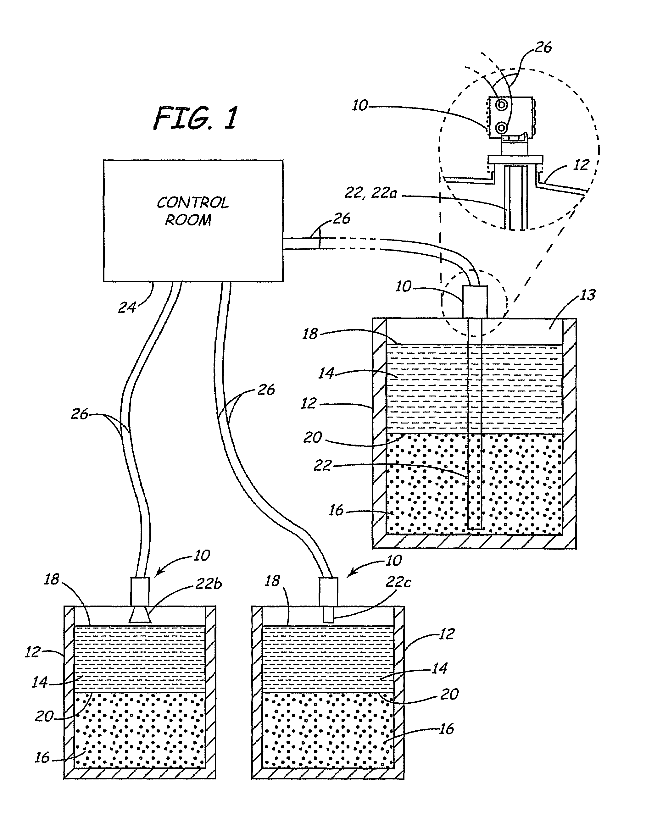
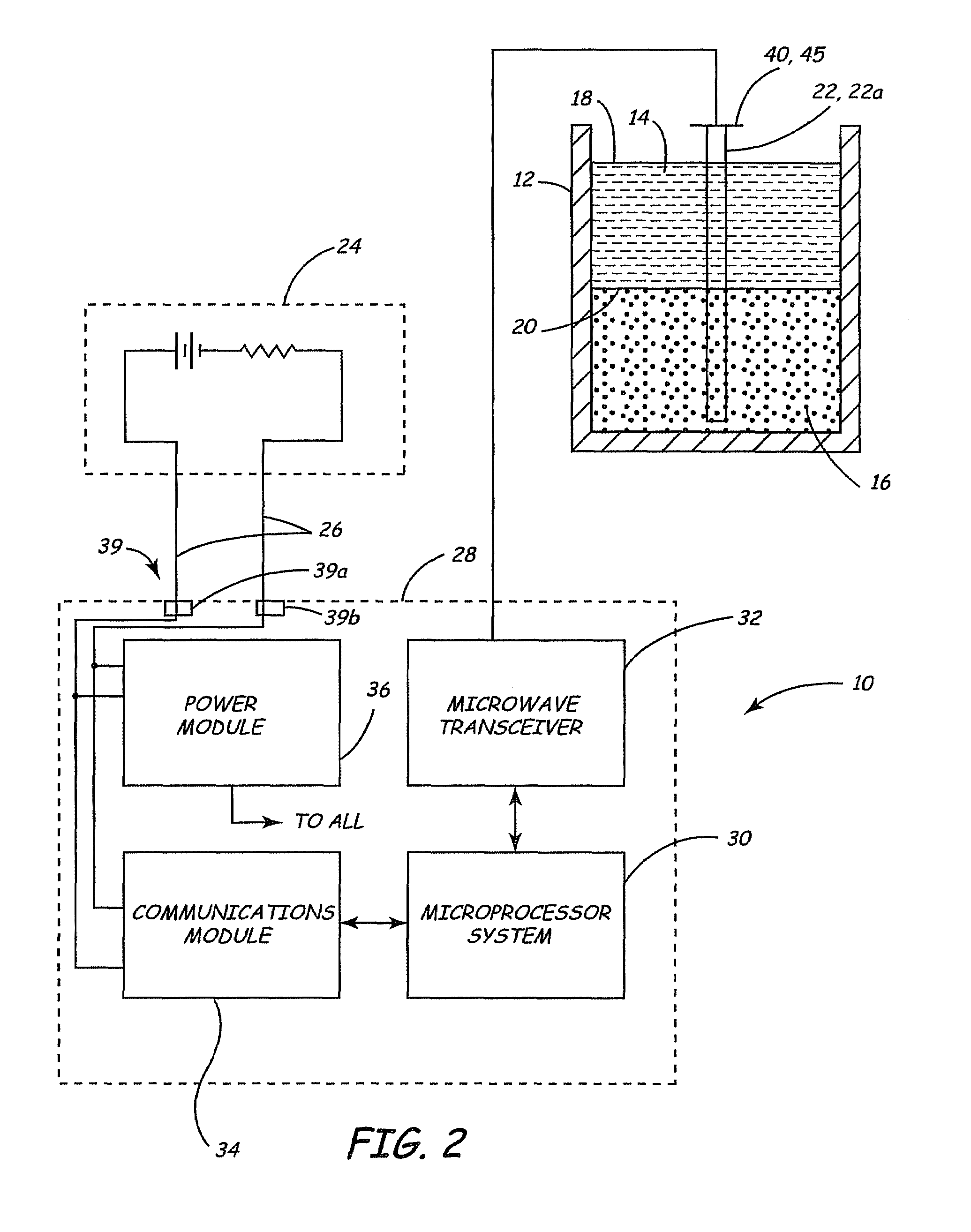
[0014]FIG. 1 shows an example of an environment in which radar level transmitters 10 generally operate. Radar level transmitters 10 can be mounted on tank 12 above, for example, first, second, and third materials 13, 14, and 16, respectively. A first material interface 18 is located at the junction of first material 13 and second material 14. A second material interface 20 is located at the junction between second material 14 and third material 16. Each radar level transmitter 10 attaches to a radar antenna 22 which generally transmits a microwave pulse into materials 13, 14, and 16.

[0015]The transmitted microwave pulse can consist of a...


PUM


Abstract

Disclosed is a method and apparatus for setting threshold values for use by a radar level transmitter to detect reflected wave pulses corresponding to portions of a transmitted microwave pulse which reflect from interfaces contained in a container. The present invention estimates these threshold values based upon various parameters. Some of these parameters can relate to properties of the materials forming the interfaces while others relate to properties of the antenna and user-defined parameters.

Description

[0001]This is a continuation-in-part of U.S. application Ser. No. 09 / 234,999, which was filed Jan. 21, 1999 and issued Mar. 6, 2001 as U.S. Pat. No. 6,198,424.BACKGROUND OF THE INVENTION[0002]The present invention relates to radar level transmitters used in the process control industry to measure levels of materials in storage vessels, such as tanks. More particularly, the present invention relates to a threshold level calculation for establishing threshold levels that can be used by a radar level transmitter to identify material interfaces which are used to calculate material levels.[0003]Radar level transmitters are used in the process control industry to measure levels of materials contained in a tank or vessel by transmitting a microwave pulse into the tank using a radar antenna, receiving a signal relating to reflections of the transmitted microwave pulse, and detecting material interfaces formed by the materials using the signal. Radar level transmitters are also generally ada...

Claims


Application Information

Patent Timeline
Patent Type & Authority Patents(United States)
IPC IPC(8): G01B21/18G01F23/00
CPCG01F23/284G01S7/2922G01S13/88
Inventor LOVEGREN, ERIC R.DIEDE, KURT C.CARLSON, RYAN R.
Owner ROSEMOUNT INC
Why Eureka
Try Eureka