Tying device

a technology of tie-down and tying rod, which is applied in the direction of flexible elements, ropes and cables for vehicles/pulleys, animal husbandry, etc., can solve the problems of inability to reuse and be easily undone, and achieve the effect of greater visual prominence, inherently, and easy for users to s

Inactive Publication Date: 2009-06-09
KABLEFLAGS
View PDF33 Cites 38 Cited by
  • Summary
  • Abstract
  • Description
  • Claims
  • Application Information

AI Technical Summary

Benefits of technology

[0006]An advantage of this aspect of the invention is that the system can allow a user to readily identify the appliance to which the cable is connected, or to identify the cable itself. This is particularly useful in situations where a plurality of appliance cables are located in close proximity to one another, for reasons of safety and to facilitate maintenance.
[0068]An advantage of this aspect of the invention is that the system can allow a user to readily identify the container and its contents. This is particularly useful in situations where a plurality of containers are located in close proximity to one another, for reasons of safety and speed of access to the container contents.

Problems solved by technology

The power cables of loose electrical equipment such as fans, power tools, computers, toasters etc are often most conveniently stored in a rolled up fashion for storage or transport by such cable ties, although these ties are not readily undone when the cabling is needed in use, and normally cannot be re-used when untied.

Method used


Image

  • Tying device
  • Tying device
  • Tying device

Examples


Embodiment Construction

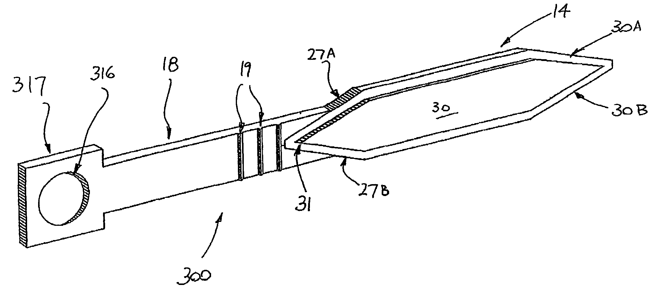
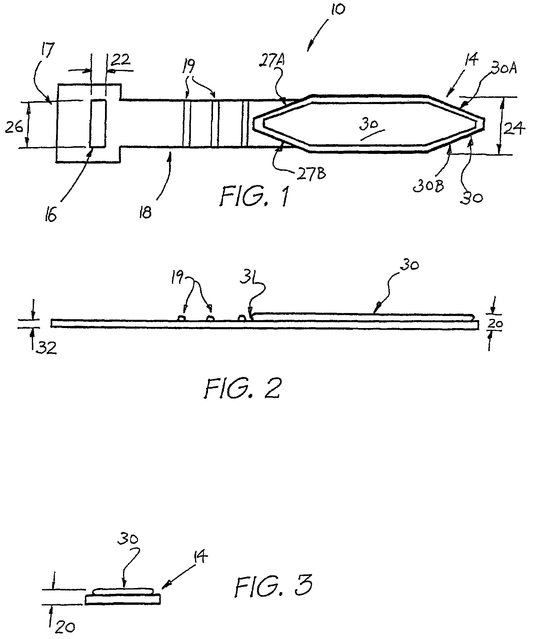
[0082]Referring to FIGS. 1 to 3, a tying device is shown in the form of an identification tag 10. The tag 10 is elongate and in use is wrapped around a cable and is releasably joined to itself to form a collar about the cable. As shown in the drawings the tag 10 has an enlarged portion shaped as a flattened octagon or diamond head 14 located at one end of a strap portion 18 of the tag 10.

[0083]In use the diamond head 14 is forcibly inserted through a hole 16 which is located in an enlarged, square-shaped opposing end portion 17 of the strap 18. The diamond head 14 has a thickness dimension 20 that is greater than the narrowest width dimension 22 of the hole 16 so that, after insertion into the hole 16, the thickness of the diamond head 14 causes that head to be retained in the hole 16. In use an end edge of the raised upper exterior surface 30 of the diamond head 14 forms a shoulder 31 which locates in seating abutment with the edges or rim of the hole 16.

[0084]In the preferred embo...


PUM


Abstract

A system is shown for differentiating two or more cables of two or more respective appliances. The system comprises respective means in the form of tag devices for positioning on and labelling each cable, wherein each tag device is provided in a differentiated form from each other tag device. The tag devices can be pre-printed or supplied with suitable indicia for positioning thereon. Such a system for identification can allow a user to more readily identify the appliance to which the cable is connected, or in the case of use of the system for labelling and identifying containers, to identify a container and its contents. This can be useful in situations where a plurality of cables, or containers, are located in close proximity to one another.

Description

[0001]This application is a U.S. National Phase of International Patent Application Ser. No. PCT / AU03 / 00665, filed May 30, 2003 which claims priority of Australian Patent Application No. PS 2636, filed May 30, 2002 and Australian Patent Application No. 2003900461, filed Jan. 29, 2003.FIELD OF THE INVENTION[0002]The present invention relates to a tying device. In one form the invention relates to a cable tying device for tying to a single cable in a looped manner, or for tying a number of cables together, and will primarily be described with reference to this context. The device can also be used for identification of the cable / s to which it is tied. It is to be understood that the invention has broad use in securing and tying as well as identification applications for all manner of mechanical or automotive apparatus, containers, cables, ropes, hoses, cords and the like.BACKGROUND ART[0003]Apparatus for tying a cable is known in the art. In particular, with electrical type cabling it ...

Claims


Application Information

Patent Timeline
Patent Type & Authority Patents(United States)
IPC IPC(8): B65D63/00A01G17/12A01K11/00B65D63/10F16B2/08F16G11/00F16L3/233G09F3/02G09F3/04G09F3/06G09F3/20H02G1/14H02G3/22
CPCA01G17/12G09F3/205H02G1/14G09F3/0295F16L2201/60Y10T24/1498
Inventor MOUGHELBAY, RABIHDIAZ, SERGIO DANIEL
Owner KABLEFLAGS
Why Eureka
Try Eureka