Swirl generator

a generator and spindle technology, applied in the direction of machines/engines, combustion air/fuel air treatment, separation processes, etc., can solve the problems of only limited space in the engine compartment for accommodating, noise generation in the intake pipe, and the size of the vehicle, so as to prevent the generation of noise and pulsation, and effectively isolate dust particles

Active Publication Date: 2009-06-09
TOYOTA BOSHOKU KK +1
View PDF7 Cites 19 Cited by
  • Summary
  • Abstract
  • Description
  • Claims
  • Application Information

AI Technical Summary

Benefits of technology

[0006]Accordingly, it is an objective of the present invention to provide a swirl generator that effectively isolates dust particles from air being drawn at a high speed and prevents the generation noise and pulsation.

Problems solved by technology

However, the size of the vehicle is substantially unchanged before and after such improvement and the engine compartment has only limited space for accommodating devices of an intake system.
This not only generates noise in an intake pipe but also disadvantageously influences an engine control system.
Specifically, separation of the air flow from the joint portions causes erroneous operation of an air flowmeter, which detects an intake air amount, or loss of the output of the engine due to decreased air intake efficiency.
Also, the separation of the air flow hampers the generation of a swirl flow.
However, this decreases swirl forming performance of the deflecting fins 93.

Method used


Image

  • Swirl generator
  • Swirl generator
  • Swirl generator

Examples


first embodiment

[0022]A swirl generator according to a first embodiment of the present invention will now be described with reference to FIGS. 1 to 7. Same or like reference numerals are given to components of the first embodiment that are the same as or like corresponding components of the prior art.

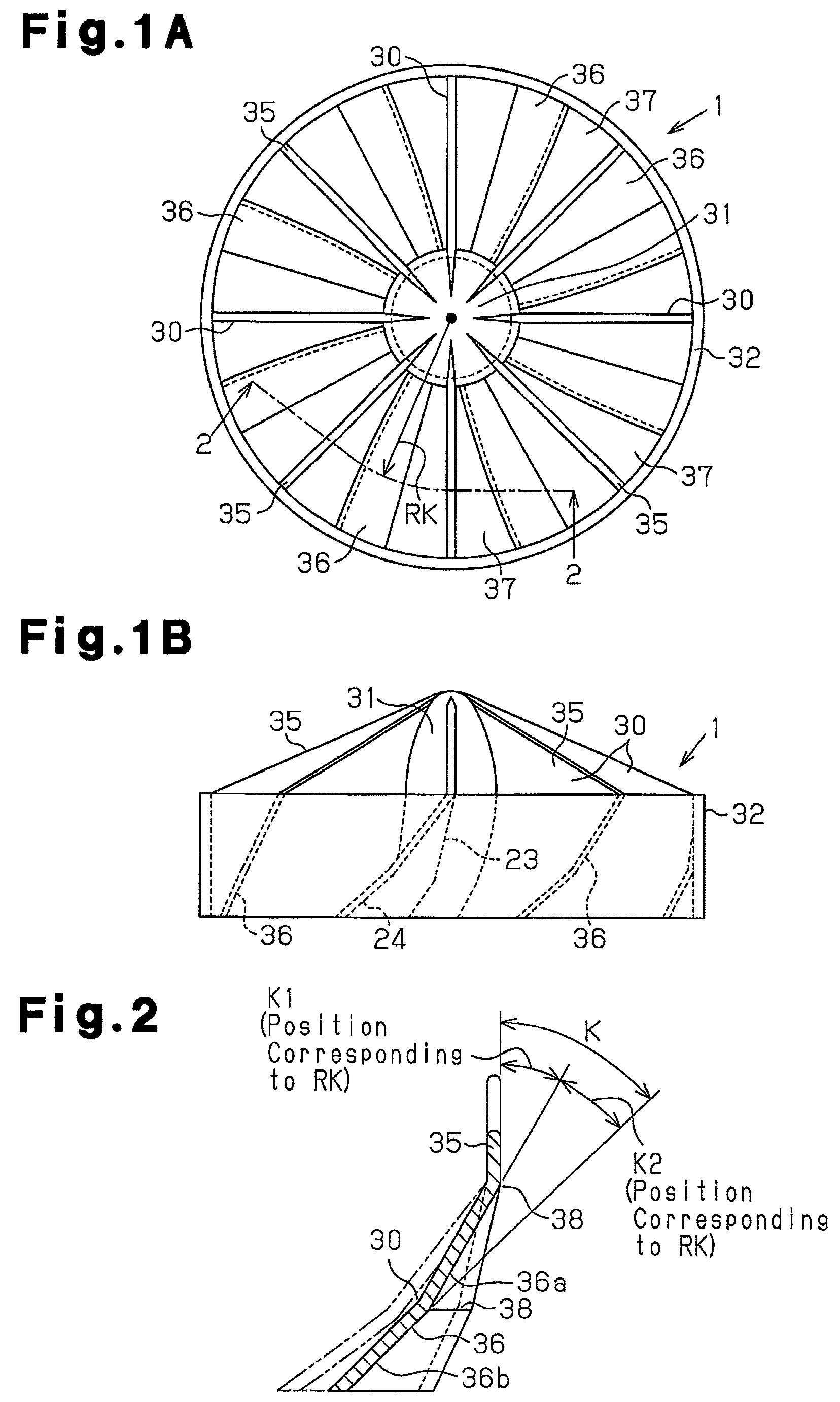
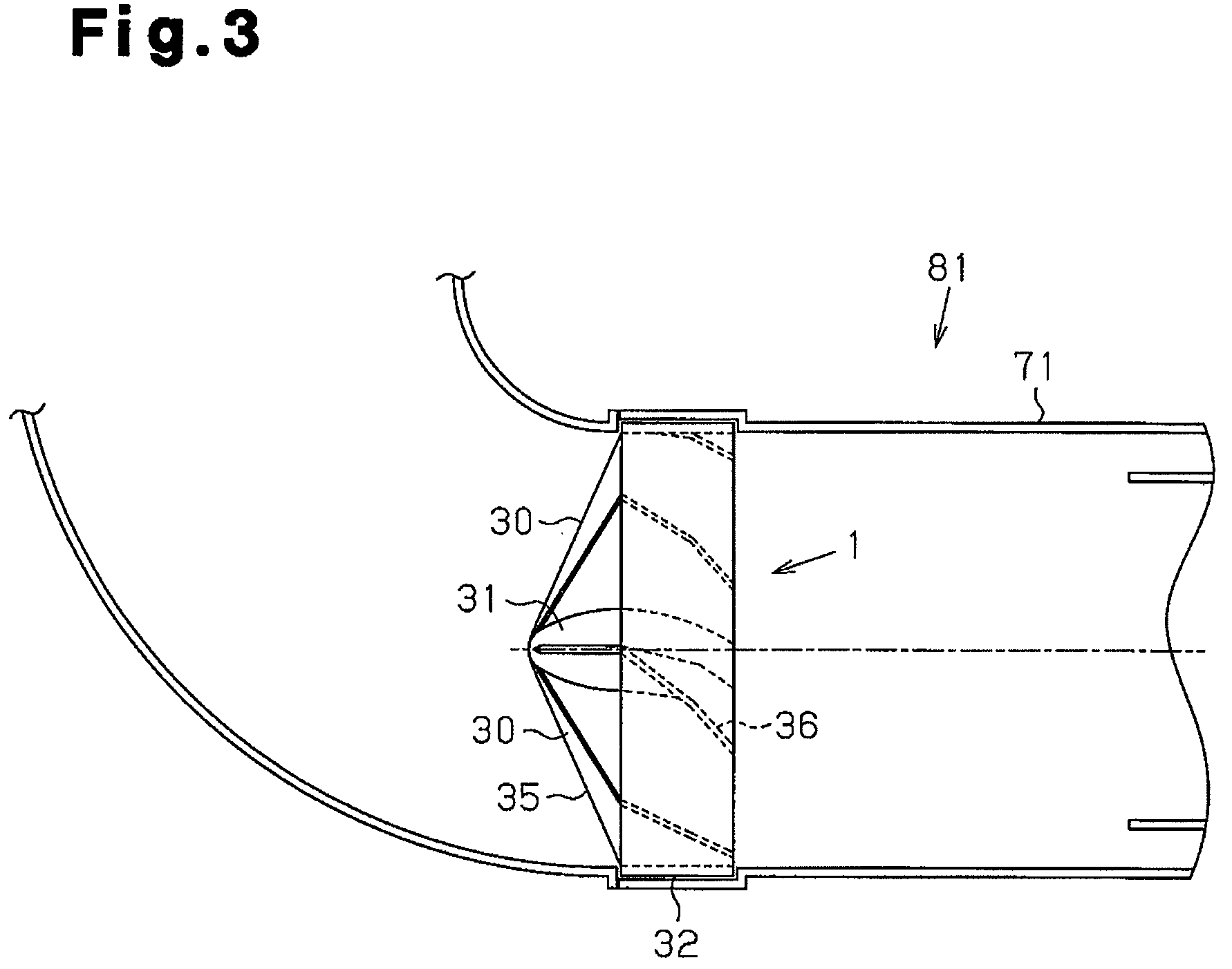
[0023]As shown in FIG. 9, a swirl generator 1 is incorporated in a duct 71. The duct 71 forms an air passage extending to a filter element 88 in a air cleaner body 86. As shown in FIG. 3, the swirl generator 1 has a nose cone 31, a ring 32, and a plurality of guide vanes 30. The nose cone 31 configures a central shaft body of the swirl generator 1. The guide vanes 30 are arranged between the nose cone 31 and the ring 32. The guide vanes 30 are formed integrally with the nose cone 31 and the ring 32. A guide fin 35 is located in an upstream portion of each of the guide vanes 30. A deflecting fin 36 is arranged in a downstream portion of each guide vane 30. Each of the guide fins 35 is formed integrally ...

example

[0034]The example used in the simulation met the following conditions.

The radius (the inner diameter) of the ring 32=32.75 mm

The first angle K1 (on the circle with the radius RK=25 mm) =30°

The second angle K2 (on the circle with the radius RK=25 mm)=20°

The diameter of the nose cone 31=25 mm

The height of the ring 32 (the deflecting fin 24)=22.4 mm

The inner diameter of the duct 71× the length of the duct 71 =99×140 mm

The intake air amount=15 m3 / min

[0035]FIG. 5 represents the result of the simulation with the example. FIG. 5 is a cross-sectional view taken along line 5-5 of FIG. 4. In the portions B1 to B5 of FIG. 4, the speed of the air flow becomes lower as the dot density becomes greater. In other words, in the dot-free portion (B5), the speed of the air flow is maximally high. The air thus flows smoothly and forms a laminar flow.

[0036]With reference to FIG. 5, according to the result of the simulation with the example, the light-toned portion B5 (the laminar flow range) extends fro...

second embodiment

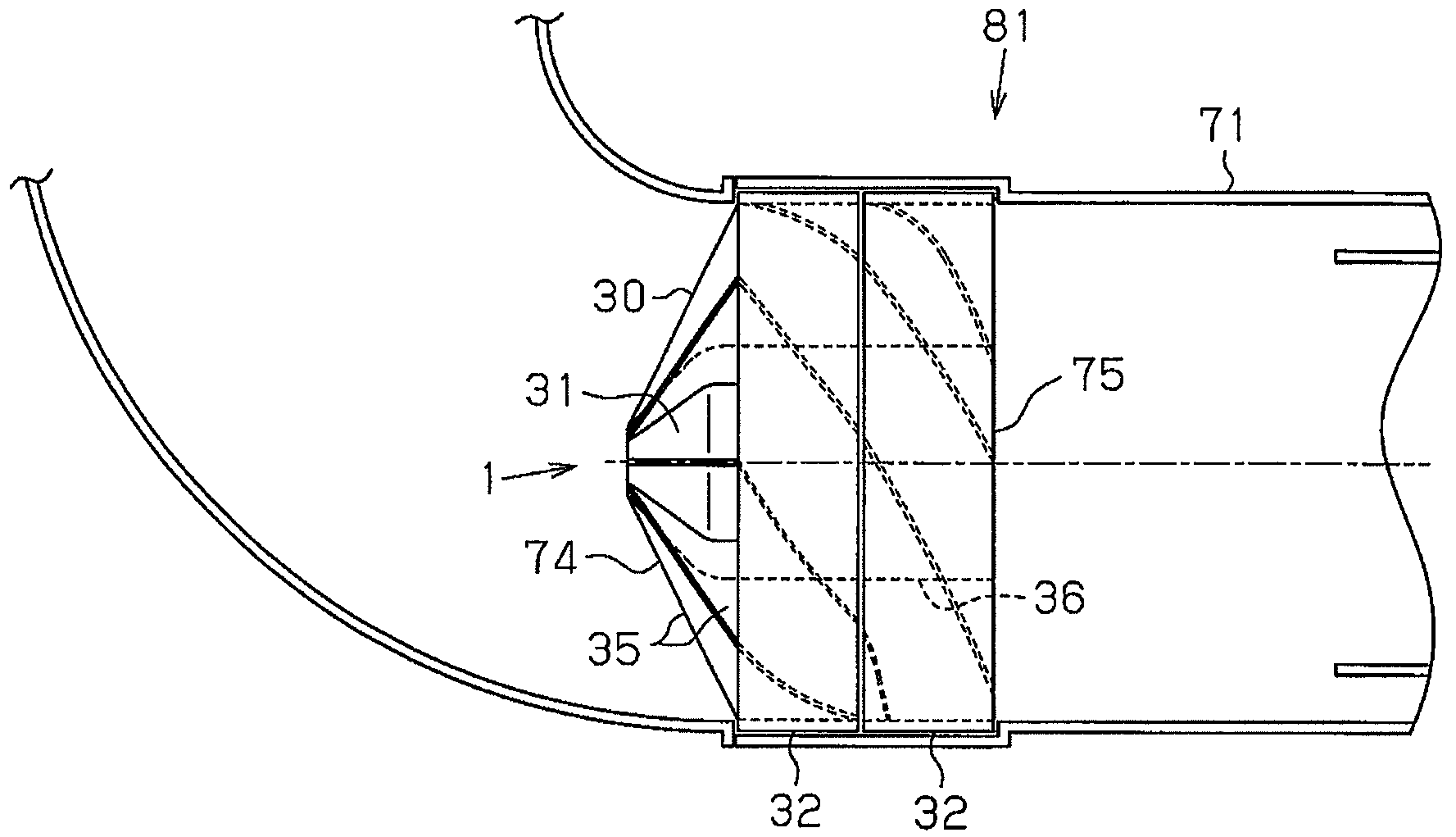
[0045]A swirl generator according to a second embodiment of the present invention will hereafter be explained. The explanation focuses mainly on the differences between the second embodiment and the first embodiment.

[0046]As shown in FIG. 8, the swirl generator 1 is formed by two separate members 74, 75, which are connected in series. The separate members 74, 75 are divided from each other along a plane perpendicular to the axis of the nose cone 31. The distal portion of the nose cone 31 and the guide fins 35 are arranged solely in the separate member 74.

[0047]The second embodiment has the following advantage.

[0048](3) If, for example, the swirl generator 1, which has an elongated shape extending along the axis of the swirl generator 1, does not have a divided structure and the upstream opening end and the downstream opening end of each clearance 37 between the corresponding adjacent pair of the deflecting fins 36 are circumferentially offset from each other, the opening ends cannot...


PUM

PropertyMeasurementUnit
inclination angleaaaaaaaaaa
inclination anglesaaaaaaaaaa

Abstract

A swirl generator is arranged in a duct through which air is sent from the exterior to an air cleaner. The swirl generator has a plurality of guide vanes, which change the flow direction of an air flow. Each of the guide vanes has a guide fin that adjusts the air flow and a deflecting fin that applies swirl force to the air flow. The deflecting fin is configured by an upstream portion and a downstream portion, which are connected together at a predetermined angle. The upstream portion and the downstream portion each have a cross section extending linearly along a cylindrical plane coaxial with a nose cone.

Description

BACKGROUND OF THE INVENTION[0001]The present invention relates to a swirl generator that centrifugally isolates dust particles from air to be fed to an engine and draws the air free from the dust particles to an air cleaner body.[0002]As shown in FIG. 9, this type of air cleaner mainly includes an inlet duct 85, a pre-cleaner 81, and an air cleaner body 86. A swirl generator 80 is located in the pre-cleaner 81. The swirl generator 80 applies swirl force to air 84 that has been introduced into the inlet duct 85. The air 84 thus forms a swirl flow 82. In this state, dust particles contained in the air 84 receive centrifugal force and thus move from the center of the pre-cleaner 81 toward an inner wall of the duct 71. The air 84 thus flows from the left-hand side to the right-hand side as viewed in FIG. 9 and is then sent to the engine. After having reached the vicinity of the inner wall of the duct 71, the dust particles in the air 84 are collected by a dust discharge valve 83, which ...

Claims


Application Information

Patent Timeline
Patent Type & Authority Patents(United States)
IPC IPC(8): F02M29/02F02M35/02
CPCB01D45/16F02M35/022F02M29/06F02M35/08
Inventor SHIBATA, MASUMIMARUYAMA, KAZUSHIGEOTSUBO, SUMINOBUHAYASHI, TOSHIO
Owner TOYOTA BOSHOKU KK
Why Eureka
Try Eureka