
Coiling machine and method for the production of a coil

a winding machine and coil technology, applied in the field of winding machines and to a winding method for producing coils, can solve the problems of only slight effort and expense for wiring the individual phases, for instance in a delta circuit or y circuit, even with a rectifier, and the load on these components would be markedly greater

Inactive Publication Date: 2009-06-09
SEG AUTOMOTIVE GERMANY GMBH
View PDF11 Cites 10 Cited by
  • Summary
  • Abstract
  • Description
  • Claims
  • Application Information

AI Technical Summary

Benefits of technology

The patent describes a winding machine for an electrical machine that has several advantages. Firstly, the machine has a carrier device that allows for easy access to each individual winding template, making it possible to produce a winding with multiple loops of wire. Secondly, the machine has a rotatable axis, which makes it possible to wind wire around the winding template without causing excessive tension or flow noises. Thirdly, the machine has a regularly ordered construction of a single coil, which ensures uniformity in the construction of the stator and winding. Fourthly, the machine has at least one separator element to prevent wire slipping and ensure a symmetrical construction of the coil. Fifthly, the machine has at least two stepped rests to accommodate different wire segments and keep the winding head small in size. Lastly, the machine has adjustable winding cheek to facilitate the removal of the winding from the winding template. Overall, the machine provides a more efficient and effective way to produce windings for electrical machines.

Problems solved by technology

The effort and expense for wiring the individual phases, for instance in a delta circuit or Y circuit, even with a rectifier, is only slight.
However, the latter would have to rotate about a markedly longer radius, so that the load on these components would be markedly greater.

Method used


Image

  • Coiling machine and method for the production of a coil
  • Coiling machine and method for the production of a coil
  • Coiling machine and method for the production of a coil

Examples


Embodiment Construction

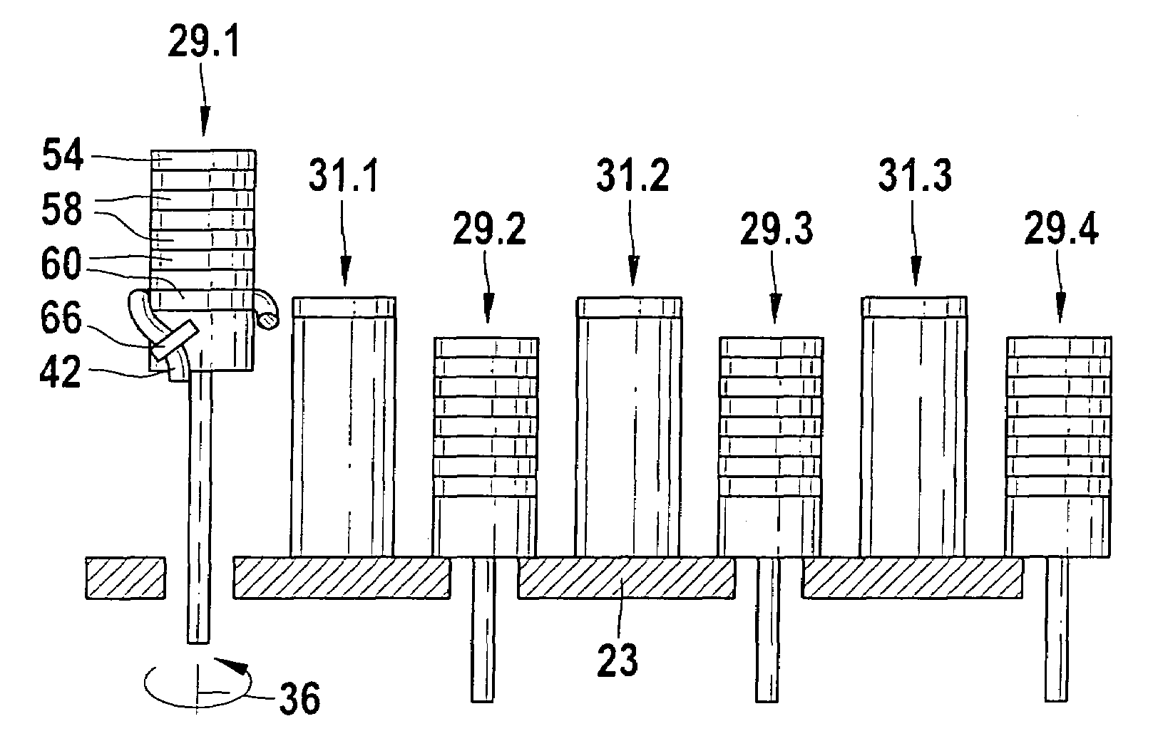
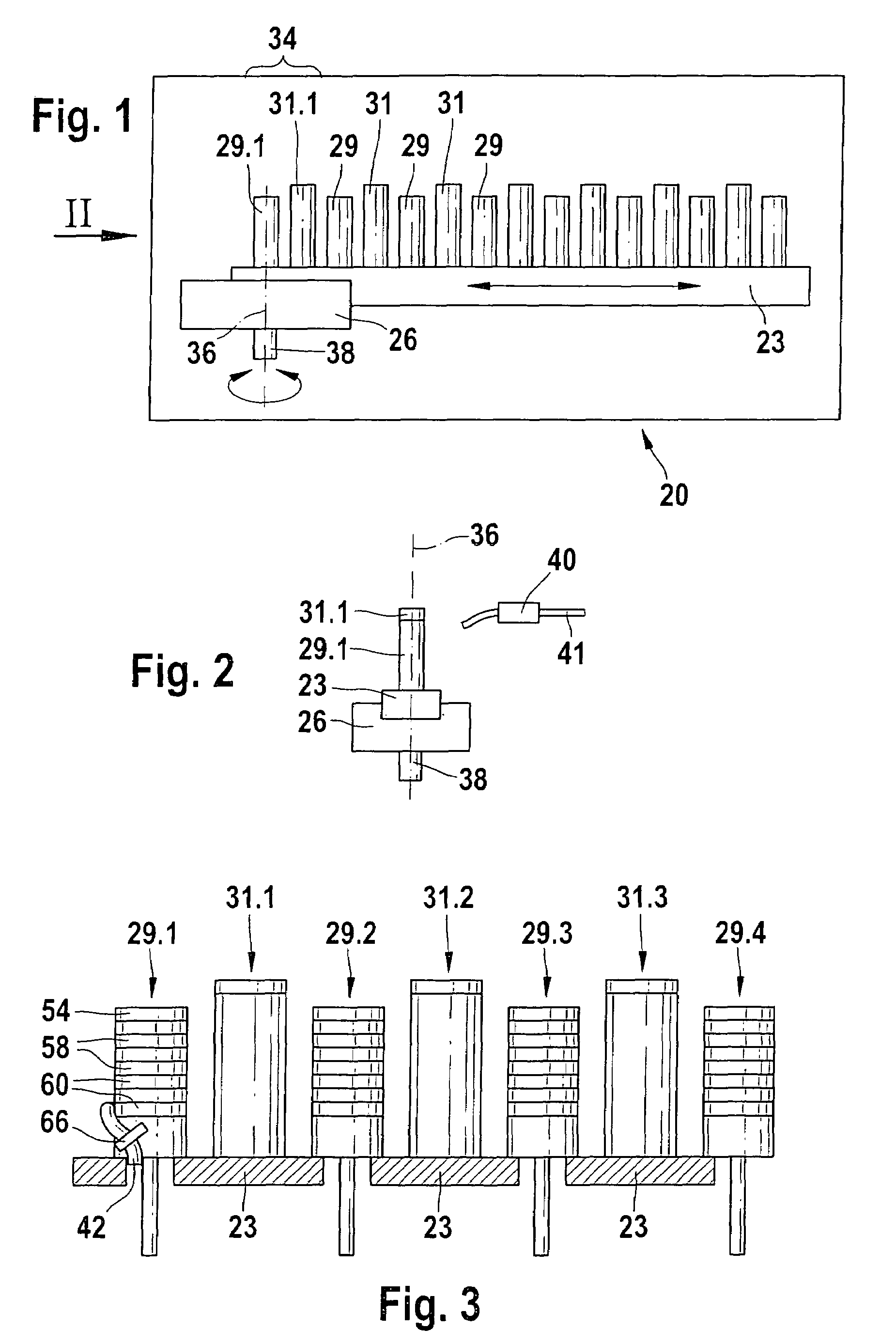
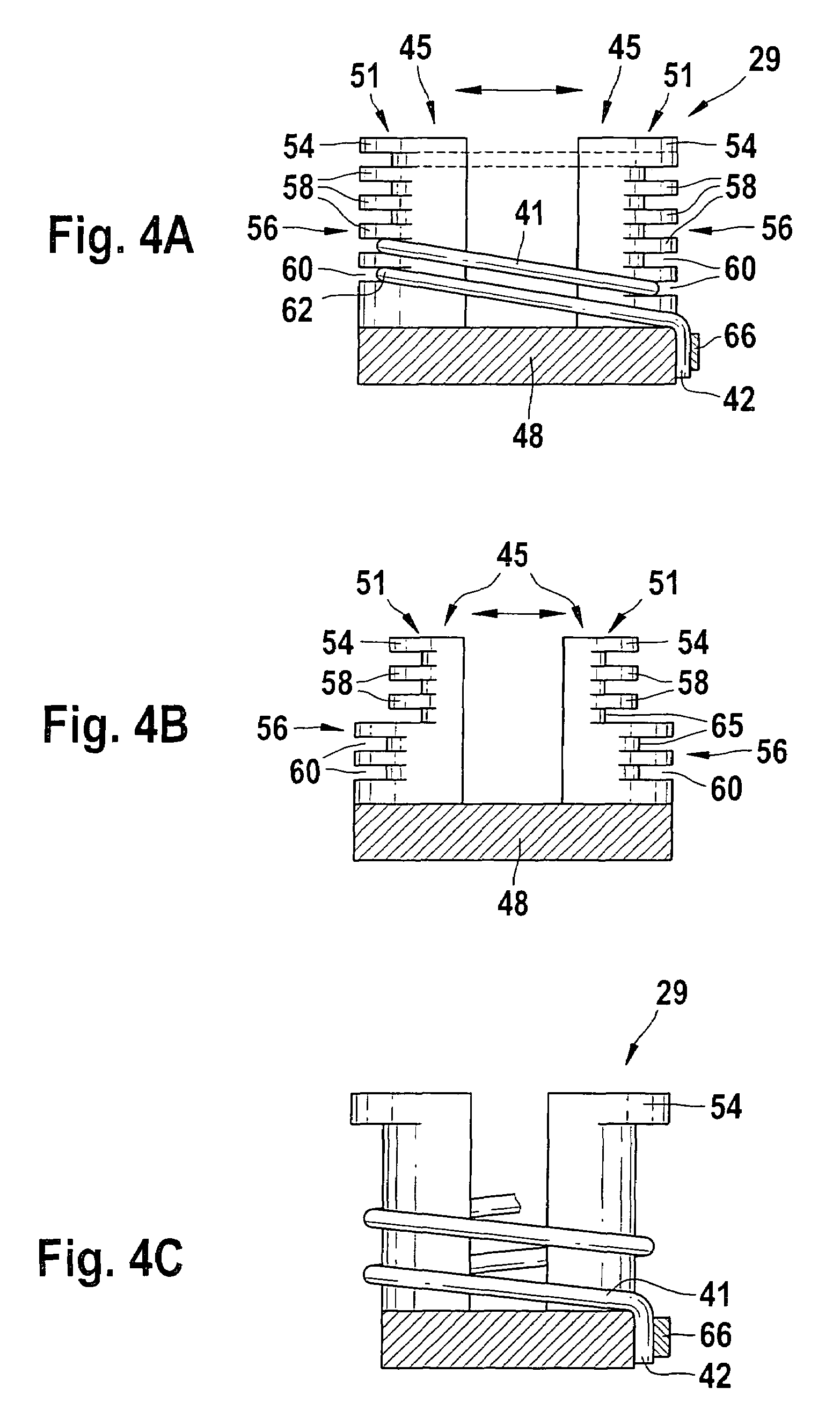
[0031]In FIG. 1, a winding machine 20 with a carrier device 23 is shown, for winding a winding for an electrical machine. The carrier device 23 is displaceably secured in a holder 26. Both winding templates 29 and deflection elements 31 are secured to the carrier device 23. A first winding template 29.1 and a first adjacent deflection element 31.1 form a first group 34, which is the minimum necessary for the function of the machine. In principle, the number of groups 34 is unlimited. The winding template 29.1 and the adjacent deflection element 31.1 are displaceable relative to one another, as will be explained in further detail for subsequent drawings. Each winding template 29 is displaceable relative to a deflection element 31. The carrier device 23 is rotatable about a pivot axis 36. To that end, the holder 26 is driven via a shaft 28 and thus carries the carrier device 23 along with it.

[0032]The pivot axis 36 is displaceable relative to the carrier device 23. In this concrete ex...


PUM

PropertyMeasurementUnit
widthaaaaaaaaaa
rotationaaaaaaaaaa
voltageaaaaaaaaaa

Abstract

A winding machine (20) has a carrier device (23) for winding a winding for an electrical machine. The carrier device (23) has at least one group (34) having a winding template (29) and an adjacent deflection element (31), and the winding template (29) and the adjacent deflection element (31) are displaceable relative to one another. In a method for producing a winding from at least one coil, at least one wire is wound around a winding template (29), producing at least one wire arrangement with at least one first coil side (68), at least one first deflection side (69), and at least one second coil (70), and a winding template (29) is displaced out of a plane for the winding process.

Description

CROSS-REFERENCE[0001]The invention described and claimed hereinbelow is also described in PCT / DE 03 / 03324, filed on Oct. 6, 2003 and DE 102 46 423.5, filed Oct. 4, 2002. This German Patent Application, whose subject mailer is incorporated here by reference, provides the basis for a claim of priority of invention under 35 U.S.C. 119(a)-(d).BACKGROUND OF THE INVENTION[0002]The invention relates to a winding machine and to a method for producing a winding.[0003]In known winding machines, a wire is wound in more or less many loops around a winding carrier or a coil. After the predetermined number of windings, the winding wire is capped; the single coil is removed and typically mounted on a stator tooth intended for it. Once this has been done for a multi-pole stator, for instance, such as one with 36 single coils, a total of 72 wire ends of the individual coils have to be interconnected in the desired manner. Thus not only is the effort for producing the single coils great, but the effo...

Claims


Application Information

Patent Timeline
Patent Type & Authority Patents(United States)
IPC IPC(8): H02K15/09H01F41/06H02K15/04
CPCH02K15/045H02K15/0457H02K15/0485H02K15/0478Y10T29/49071Y10T29/49012H02K15/0442
Inventor STROEBEL, WOLFGANGKIRSCHNER, ROLAND
Owner SEG AUTOMOTIVE GERMANY GMBH
Learn More