Optical film and backlight module, display device and electro-optical device including thereof

a technology of backlight module and optical film, which is applied in the field of optical film, can solve the problems of lcd panel trade-off, uneven expansion of films, and a burden on both fabrication time and materials cost, and achieve the effects of reducing the use of adhesive materials, improving the fixed optical film of the backlight module, and increasing the degree of freedom

Active Publication Date: 2009-06-09
AU OPTRONICS CORP
View PDF13 Cites 14 Cited by
  • Summary
  • Abstract
  • Description
  • Claims
  • Application Information

AI Technical Summary

Benefits of technology

[0014]The present invention of the backlight module is able to improve the fixed of the optical films of the backlight module. It further provides more degree of freedom for the optical films in thermal expansion. The advantages of the backlight module further include decreasing the use of the adhesive material cause the cost-down as well as reducing failure ratio of the manufacture and reworked ratio of the backlight module. Furthermore, the backlight module avoids the problem of material mixing and other problems induced by degumming of the adhesive tape.

Problems solved by technology

However, there is a conflict / trade-off in LCD panels between the downscaling of weight and size, and the robustness of the structure.
However, the optical films tightly fixed on the plastic frame 102 solves the problem of the displacement of the optical films but results in uneven expansion of the films when the temperature varies whatever also destroys the uniformity of the LCD.
It is absolutely a burden to both the fabrication time and the cost of materials.

Method used


Image

  • Optical film and backlight module, display device and electro-optical device including thereof
  • Optical film and backlight module, display device and electro-optical device including thereof
  • Optical film and backlight module, display device and electro-optical device including thereof

Examples


first embodiment

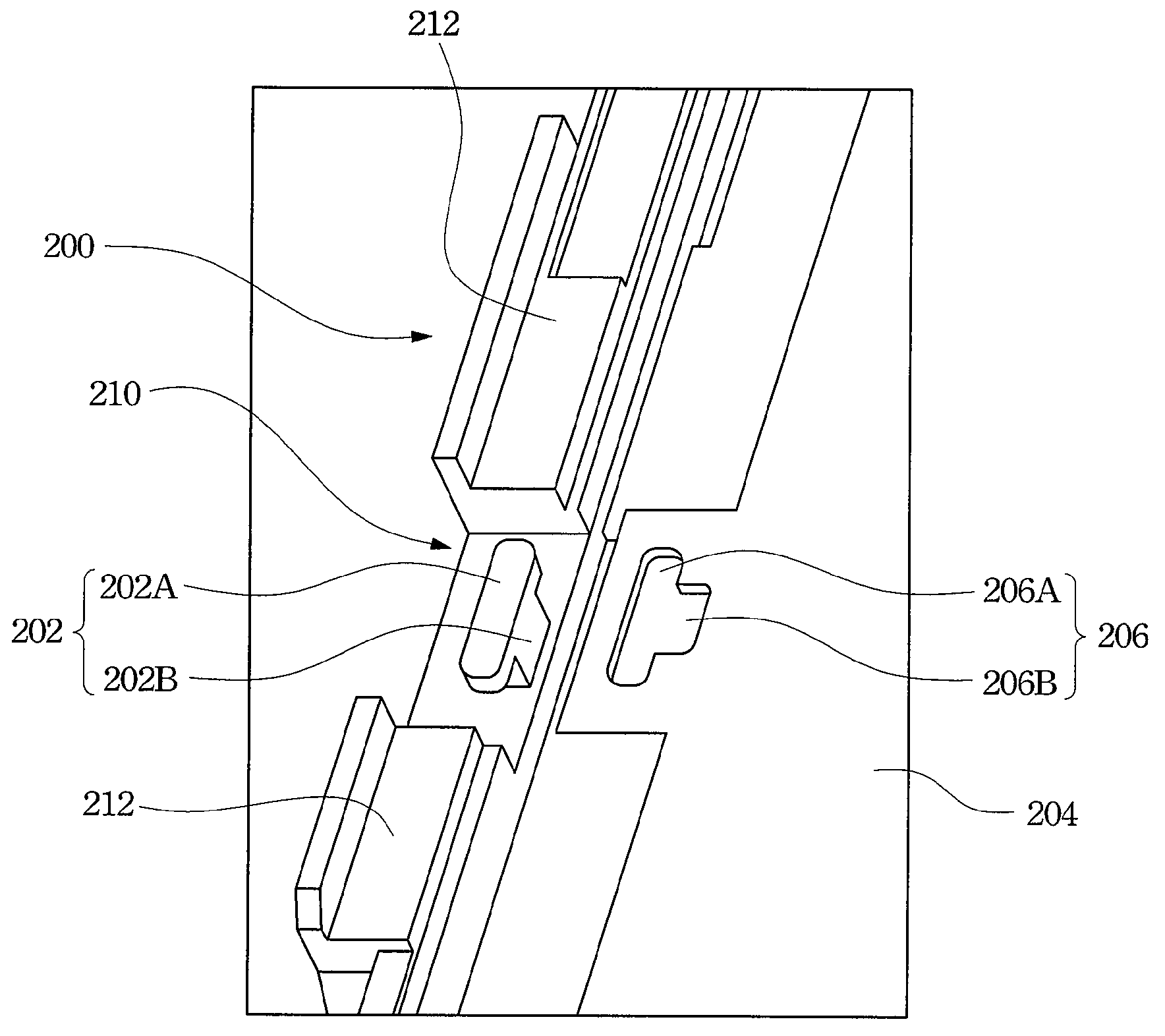
[0028]Referring to FIG. 4 illustrates a diagram of the present invention. There is a fixed structure 202 on a top surface at a side of the frame 200. The fixed structure 202 includes a fixed part 202A and a connected part 202B connecting the surface at the side of the frame 200 and is the fixed part 202A. Preferred, the width of the fixed part 202A is substantially greater than the width of the connected part 202B. The connected part 202B of the fixed structure 202 is preferably but not limited to couple to a substantially center region of the fixed part 202A. For example, the connected part 202B can couple to a place is substantially strayed from the center region of the fixed part 202A, an end is substantially away from the center region of the fixed part 202A (not shown), or can be located at other position. A shape of the fixed part 202A in a top view may preferably but not necessarily be an substantially ellipse. The shape of the fixed part 202A in a top view may otherwise be a...

second embodiment

[0032]In second embodiment, as illustrated in FIG. 7, in an accommodated part 208 of the optical film 204. The optical film having a body (not shown) and the accommodated part connects to the body. The accommodated parted 208 has the first portion 208A and the second portion 208B to form a shape of substantially inverse T or other shapes. In other words, the first portion 208A is adjacent to the body and the second portion 208B is away from the base. Besides, the fixed part 202A and the connected part 202B of the fixed structure 202 are not limited to the structures shown in FIG. 4 and FIG. 5. For the fixed structure of the present invention, the width of the fixed part is substantially greater than the width of the connected part. Hence after passing through the fixed part, the first portion of the accommodated part of the optical film may push the optical film along a predetermined direction, such that the second portion of the accommodated part is accommodate the connected part. ...


PUM


Abstract

A backlight module is provided. The backlight module includes a frame, a fixed structure and at least one optical film. The fixed structure includes a fixed part and a connected part connects to the surface and the fixed part. The width of the fixed part is substantially greater than the width of the connected part. The at least one optical film includes an accommodated part comprising a first portion and a second portion adjoins to the first portion. The width of the first portion is substantially greater than or substantially equal to the fixed part, and the width of the second portion is substantially greater than or substantially equal to the width of the connected part.

Description

RELATED APPLICATIONS[0001]This application claims the benefits of Taiwan Application No. 96101652, filed Jan. 16, 2007, the contents of which are herein incorporated by reference in its.BACKGROUND[0002]1. Field of Invention[0003]The present invention relates to an optical film and, more particularly, to an optical film of a backlight module, a display device, and an electro-optical device with the backlight module.[0004]2. Description of Related Art[0005]With progress of electro-optical technologies and the coming of digital times to cause the business of liquid crystal display (LCD) is flourishing. The LCD having the advantages of high quality of the image, small volume, light weight, low drive voltage, and low power consumption, LCD is broadly applied in consumer communication products or electronic products, such as personal digital assistants (PDAs), mobile phones, camcorders, notebooks, desktop computers, automobile displays, and projection televisions, and replaces cathode ray...

Claims


Application Information

Patent Timeline
Patent Type & Authority Patents(United States)
IPC IPC(8): F21V7/04
CPCG02B6/0088G02F1/133608G02F1/133606G02F2201/465
Inventor YUAN, SHIH-WUPAN, CHIH-LIANGWANG, I-JAN
Owner AU OPTRONICS CORP
Why Eureka
Try Eureka