Dynamic temperature compensation for a digitally controlled oscillator using dual MEMS resonators

a technology of dynamic temperature compensation and digital control, which is applied in the direction of process and machine control, optical radiation measurement, pulse generator, etc., can solve the problems of large error in output frequency, complex and expensive circuits of the inability to achieve fast and precise electronic temperature sensing circuits. even more complex and expensive to implemen

Active Publication Date: 2009-06-09
SITIME
View PDF17 Cites 36 Cited by
  • Summary
  • Abstract
  • Description
  • Claims
  • Application Information

AI Technical Summary

Benefits of technology

[0009]One advantage of the disclosed system is that dynamic and precise temperature compensation may

Problems solved by technology

One major drawback to using this type of temperature compensation system is that obtaining digital temperature measurements with a precision better than 1 degree Centigrade (° C.) from an electronic temperature sensor requires complex and expensive circuits that consume relatively large amounts of power.
In addit

Method used


Image

  • Dynamic temperature compensation for a digitally controlled oscillator using dual MEMS resonators
  • Dynamic temperature compensation for a digitally controlled oscillator using dual MEMS resonators
  • Dynamic temperature compensation for a digitally controlled oscillator using dual MEMS resonators

Examples


Embodiment Construction

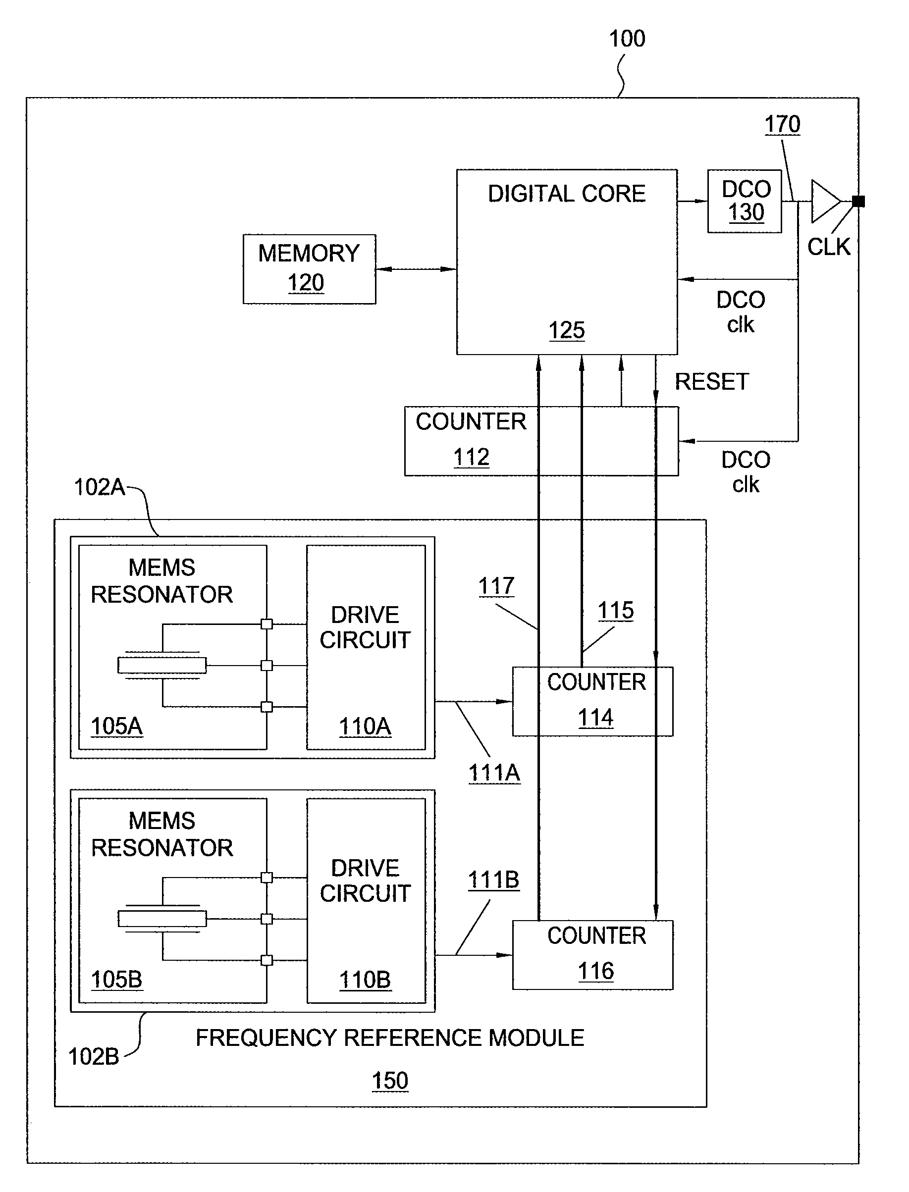
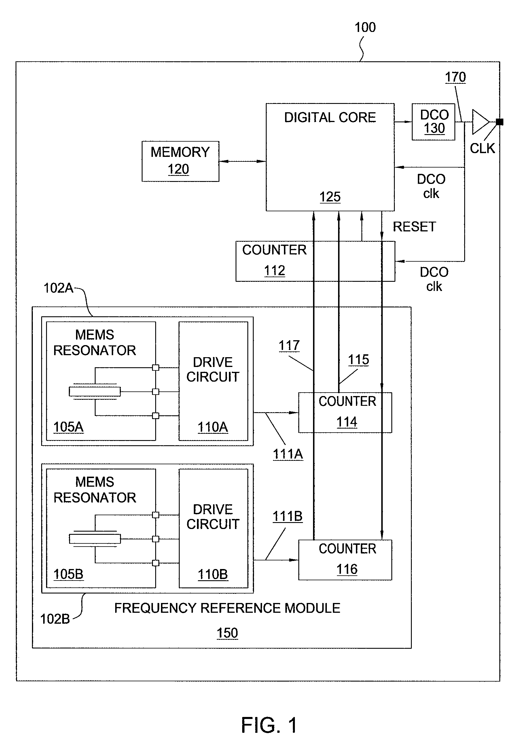
[0017]FIG. 1 is a conceptual illustration of a frequency source 100, according to one embodiment of the present invention. As shown, the frequency source 100 includes, without limitation, a digitally controlled oscillator (DCO) 130 that generates an output signal 170 (referred to here in as a “DCO output signal”), a frequency reference module 150, a digital core 125, a counter 112, and a memory 120. Typically, the frequency of the DCO output signal 170 is temperature-dependent and varies in an unpredictable manner as a result of temperature fluctuations within the system. As described in greater detail below, the digital core 125 and the counter 112 form a servo control loop for maintaining the frequency of the DCO output signal 170 at a target value set by the requirements of a particular application, despite temperature fluctuations. Arrows indicate electronic signal paths within the frequency source 100. The frequency source 100 may be implemented in any type of electronic device...


PUM


Abstract

A method for generating a temperature-compensated timing signal that includes counting, within an update interval, a first number of oscillations of a first micro-electromechanical (MEMS) resonator, a second number of oscillations of a second MEMS resonator and a third number of oscillations of a digitally controlled oscillator (DCO), computing a target DCO count based on the first number and second number of oscillations, computing a loop error signal based on the target DCO count and the third number of oscillations, and modifying an output frequency of a temperature-dependent (DCO) timing signal based on the loop error signal. The duration of the update interval may also be modified based on temperature conditions, and the update interval may also be interrupted and the output frequency immediately adjusted, if a significant temperature change is detected. Thus, dynamic and precise temperature compensation is achieved that accommodates constant, slowly changing, and rapidly changing temperature conditions.

Description

BACKGROUND OF THE INVENTION[0001]1. Field of the Invention[0002]Embodiments of the present invention generally relate to temperature compensated oscillators and, more specifically, to dynamic temperature compensation for a digitally controlled oscillator using dual MEMS resonators.[0003]2. Description of the Related Art[0004]Many electronic devices include timing circuitry that usually runs continuously so that accurate time and date information, among other things, may always be maintained. Oscillators are commonly used in the timing circuitry of such devices to produce the required timing signal. However, with many mechanical oscillators, the resonant frequency of the signal produced by the oscillator depends upon temperature. Consequently, oscillator circuits usually require some sort of temperature compensation functionality.[0005]A typical temperature compensation system includes a temperature sensor configured to detect temperature changes at regular intervals and a frequency ...

Claims


Application Information

Patent Timeline
IPC IPC(8): H03L1/00H03B5/30
CPCH03H9/02448H03L1/026
Inventor LU, CRISTKLAASSEN, ERNOPERUMAL, SATHI
Owner SITIME
Why Eureka
Try Eureka