Terminal board for temperature compensation of thermocouple

a temperature compensation and terminal board technology, applied in the direction of thermometer testing/calibration, instruments, heat measurement, etc., can solve the problems of increasing temperature error, reducing temperature error, and difficult to attach the temperature compensation sensor to the terminal board, so as to reduce the influence of heat generated within the casing, reduce the effect of temperature error and accurate temperature measuremen

Active Publication Date: 2019-05-07
AUTONICS
View PDF7 Cites 1 Cited by
  • Summary
  • Abstract
  • Description
  • Claims
  • Application Information

AI Technical Summary

Benefits of technology

[0013]Accordingly, the present invention has been made keeping in mind the above problems occurring in the prior art, and an object of the present invention is to provide a terminal board for thermocouple temperature compensation, which has a simple structure and is capable of accurate temperature compensation.
[0017]a sensor pin unit fixed on the top surface of the compensation sensor PCB through soldering and having a pair of connection pins curved for connection between output of the temperature compensation sensor and the temperature compensation circuit of the circuit board, wherein the temperature compensation sensor is disposed close to a connection unit between the compensation conductor and the terminal unit, thereby minimizing the influence of heat generated within a casing, reducing a temperature error, and enabling accurate temperature measurement.

Problems solved by technology

Accordingly, a temperature error is generated because the temperature measured by the temperature detector is reduced by the temperature of the terminal board.
In a conventional technology, it is technically difficult to attach the temperature compensation sensor to the terminal board.
However, the conventional technology has a problem in that a temperature error is increased because the temperature compensation sensor is far spaced part from the location of the terminal board to which the compensation conductor is connected.
Accordingly, an error value varies over time due to a temperature difference between a temperature at the terminal board to which the compensation conductor is connected and a temperature measured by the temperature compensation sensor, thereby making it difficult to correct a temperature measured by the thermocouple.
However, the disclosed structure is problematic in that the structure is complicated, and a manufacturing cost and a process are increased because a fixing member for fixing the temperature compensation sensor must be separately fabricated.
Furthermore, there is a possibility that a temperature error may occur due to heat generated from the inside of a casing 20 because the temperature compensation sensor 51 is disposed within the terminal board installed in the casing 20.
Furthermore there is a problem in that a temperature error is increased if the cover 52 covering the temperature compensation sensor 51 does not well come into contact with the terminal board due to the deformation of the terminal board, the casing 20, and the holder 50 because the terminal board and the temperature compensation sensor come into contact with each other.

Method used


Image

  • Terminal board for temperature compensation of thermocouple
  • Terminal board for temperature compensation of thermocouple
  • Terminal board for temperature compensation of thermocouple

Examples


Embodiment Construction

[0025]An embodiment of the present invention is described with reference to the accompanying drawings in order for the present invention to be fully understood. The embodiment of the present invention may be modified in various forms, and the range of right of the present invention should not be construed as being limited to the following exemplary embodiment. The embodiment of the present invention is intended to fully describe the present invention to a person having ordinary skill in the art. Accordingly, the shapes, etc., of elements in the drawings may have been enlarged in order to highlight a more full description. It is to be noted that the same reference numerals are used to denote the same elements in the drawings. Furthermore, a detailed description of the known functions or constructions that may make the gist of the present invention is omitted.

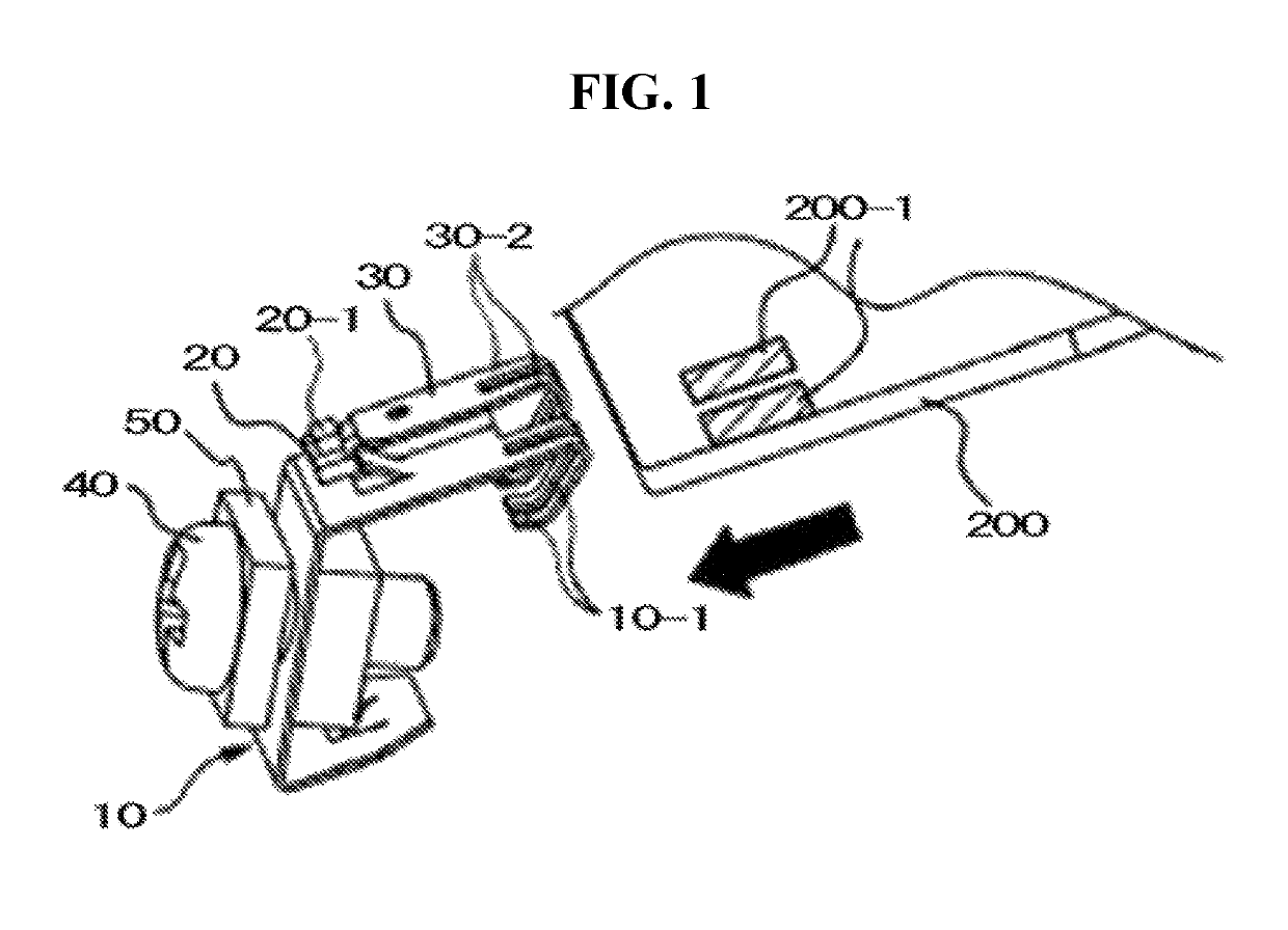
[0026]As shown in FIG. 1, a terminal board for thermocouple temperature compensation according to an embodiment of the present ...


PUM

PropertyMeasurementUnit
temperatureaaaaaaaaaa
temperature detectoraaaaaaaaaa
temperature erroraaaaaaaaaa

Abstract

The present invention provides a terminal board for temperature compensation of a thermocouple, the terminal board comprising: -shaped terminal unit for connecting a compensation lead wire of the thermocouple to a PCB contact terminal connected to a control circuit of a circuit board so as to allow accurate temperature compensation of the thermocouple, the terminal unit having a pair of curved connection pins; a small-sized compensation sensor PCB which has a chip type temperature sensor for compensation at one end of the upper side thereof, an upper soldering surface which is soldered to a sensor pin unit for electrically connecting an output of the temperature sensor for compensation, and a lower soldering surface which is soldered to the terminal unit; and an L-shaped sensor pin unit for soldering the compensation sensor PCB together with the terminal unit, the sensor pin unit having a pair of rounded connection pins for contact-connection of the output of the temperature sensor for compensation to the temperature compensation sensor of the circuit board.

Description

CROSS REFERENCE TO RELATED APPLICATIONS[0001]This application is the National Phase of PCT / KR2015 / 008324 filed on Aug. 10, 2015, which claims priority under 35 U.S.C. § 119(a) to Patent Application No. 10-2014-0104680 filed in the Republic of Korea on Aug. 12, 2014, all of which are hereby expressly incorporated by reference into the present application.BACKGROUND OF THE INVENTION[0002]Field of the Invention[0003]The present invention relates to a terminal board for thermocouple temperature compensation, which corrects a temperature error generated in the terminal board for connecting thermocouples in a thermostat and a thermometer and, more particularly, to a terminal board for thermocouple temperature compensation, which is capable of accurately compensating for a temperature by measuring a temperature at the terminal board connecting thermocouples and incorporating the measured temperature in a measured temperature of the thermocouple.[0004]Discussion of the Related Art[0005]A th...

Claims


Application Information

Patent Timeline
Patent Type & Authority Patents(United States)
IPC IPC(8): G01K1/00G01K7/02G01K7/00G01K1/20G01K1/14
CPCG01K1/20G01K7/02G01K1/14G01K1/16G01K15/00
Inventor PARK, HWAN KI
Owner AUTONICS
Why Eureka
Try Eureka