Common-aperture optical system incorporating a light sensor and a light source

a technology of light sensor and light source, which is applied in the field of common aperture optical system incorporating a light sensor and a light source, can solve the problems of difficulty in combining the optics of the two applications into a single telescope, difficulty in aligning and paralleling the boresights of these two separate telescopes, and affecting the accuracy of the image, so as to avoid misalignment and lighten the weight

Active Publication Date: 2009-06-09
RAYTHEON CO
View PDF20 Cites 11 Cited by
  • Summary
  • Abstract
  • Description
  • Claims
  • Application Information

AI Technical Summary

Benefits of technology

[0005]The present approach provides an apparatus and technique for achieving precise boresight alignment of an input light beam to a light sensor and an output light beam from a light source or transmitter. A common aperture telescope is used for both the incoming and outgoing beams. An injection technique allows the outgoing output light beam to be injected along the beam path. The common aperture optical system is more compact, lighter, and less expensive than a two-aperture optical system to perform the same functions, and also maintains its alignment under a wide variety of conditions. The use of reflective optics in the common aperture telescope avoids chromatic aberration when the incoming and outgoing beams are of significantly different wavelengths, as is often the case.
[0010]With this design, the output light beam is injected into the inverse of the beam path between the secondary mirror and the tertiary mirror of the reflective telescope. The diverger lens converts the collimated laser output light beam into a diverging beam to correspond to the divergence of the inverse of the beam path at the location of the injection. The divergence of the laser beam is preferably matched to the full size of the light beam at the point of injection and thence to the numerical aperture of the primary-secondary mirror pair of the telescope. In this preferred approach, the output light beam is expanded to the full numerical aperture of the telescope, reducing the potential for air breakdown that may otherwise occur with a high-power-density laser beam.
[0012]The present approach provides an optical system that is used to receive an input light beam that is imaged, and transmit an output afocal light beam through a single telescope having an aperture that is common to the input light beam and the output light beam. The input light beam and the output light beam are therefore necessarily aligned along a common boresight. This configuration avoids any misalignment that might otherwise occur during service. Because the output light beam may use the entire aperture of the telescope, the beam divergence of the output light beam is smaller, as much as a factor of two as compared with alternative approaches. This advantage is particularly important when there is a very limited aperture size for the laser light source path through the telescope in order to meet the constraints of package size. It would be difficult to have a laser source aperture size greater than half the sensor aperture size. This optical system is also physically smaller and lighter in weight than alternatives that use different telescopes for the two light beams.

Problems solved by technology

However, keeping the boresights of these two separate telescopes aligned and parallel is challenging, particularly in rugged conditions and in adverse environments such as those where the temperature changes significantly so that there are possible thermal expansion differences in the mounting structures of the telescopes.
While this single-telescope approach is appealing, it is difficult to implement where the character of the two optical signals is different.
For example, if the light sensor is sensing an image of focused, relatively low-intensity light of a first wavelength, and the light source is afocally transmitting relatively high-intensity light of a second wavelength, such as in the case of a laser rangefinder or laser designator, it is difficult to combine the optics for the two applications into a single telescope.

Method used


Image

  • Common-aperture optical system incorporating a light sensor and a light source
  • Common-aperture optical system incorporating a light sensor and a light source
  • Common-aperture optical system incorporating a light sensor and a light source

Examples


Embodiment Construction

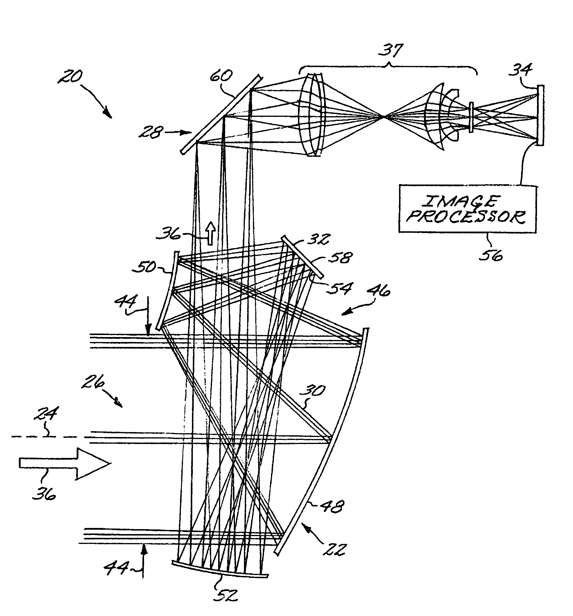
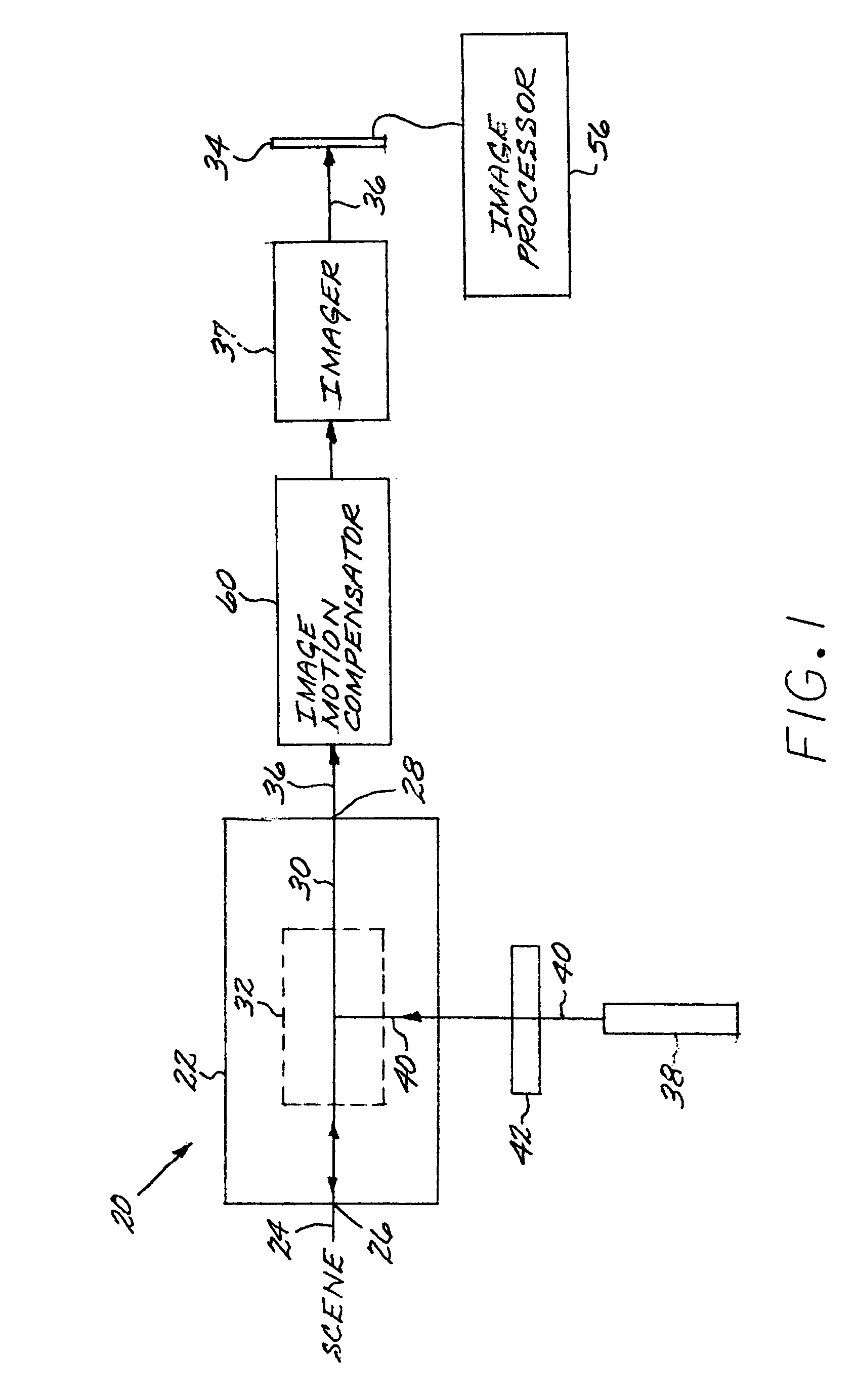
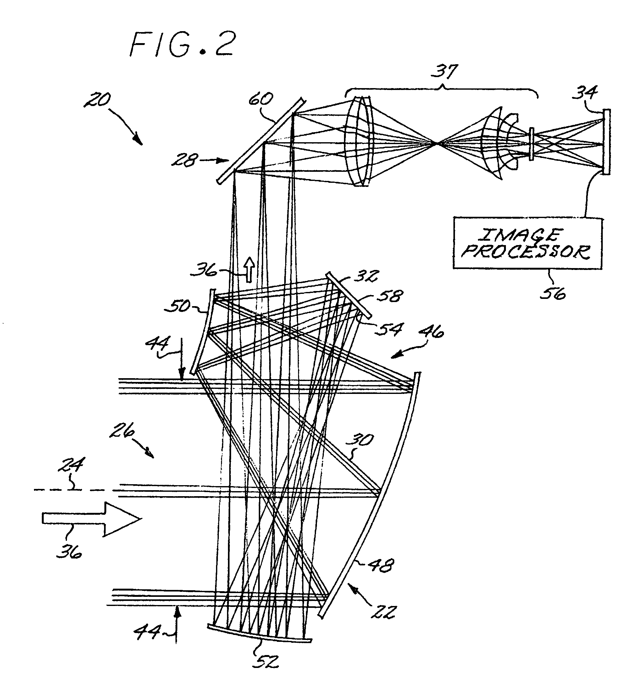
[0017]FIG. 1 depicts in block-diagram form a preferred form of a common-aperture optical system 20. The common-aperture optical system 20 includes a reflective telescope 22 having a common boresight 24, an entrance pupil 26 of the reflective telescope 22, an exit pupil 28 of the reflective telescope 22, and a beam path 30 extending from the entrance pupil 26 to and beyond the exit pupil 28. A beam splitter 32 intersects the beam path 30 so that the beam path 30 is incident upon the beam splitter 32. A light sensor 34, preferably an imaging light sensor 34, is positioned to receive an input light beam 36 traveling along the beam path 30 after the beam path 30 intersects the beam splitter 32 and passes the exit pupil 28 of the reflective telescope 22. The output of the light sensor 34 is provided to an image processor 56. Preferably but not necessarily, an image motion compensator 60 is placed at or near the exit pupil 28 in the collimated beam space before the input light beam 36 rea...


PUM


Abstract

A common-aperture optical system includes a reflective telescope having a common boresight, an entrance pupil, an exit pupil, and a beam path extending from the entrance pupil to and beyond the exit pupil. A beam splitter intersects the beam path so that the beam path is incident upon the beam splitter. A light sensor is positioned to receive an input light beam traveling along the beam path after the beam path intersects the beam splitter and passes the exit pupil of the reflective telescope. A light source produces an output light beam incident upon the beam splitter and positioned to inject the output light beam into an inverse of the beam path and toward the entrance pupil of the reflective telescope. A diverger corrects at least one of the input light beam and the output light beam.

Description

[0001]This invention relates to an optical system and, more particularly, to an optical system in which a light sensor and a light source operate through the same optics and have a common boresight.BACKGROUND OF THE INVENTION[0002]If an optics system requires both the sensing of a target location in a scene by a light-sensitive sensor and the transmission of light to the same location, the boresights of the sensor and the transmitter must be accurately aligned. One possible approach is to use two separate telescopes, one to gather the light for the sensor and the other to direct the output light, and to maintain a fixed parallel boresight arrangement of the two telescopes. However, keeping the boresights of these two separate telescopes aligned and parallel is challenging, particularly in rugged conditions and in adverse environments such as those where the temperature changes significantly so that there are possible thermal expansion differences in the mounting structures of the te...

Claims


Application Information

Patent Timeline
Patent Type & Authority Patents(United States)
IPC IPC(8): G02B23/00G02B27/14
CPCF41G1/38F41G3/065F41G3/326G01S7/4812G02B17/0615G02B23/105
Inventor CHEN, CHUNGTE W.ANDERSON, J. STEVE
Owner RAYTHEON CO
Why Eureka
Try Eureka