Imaging device and therapy facility having such a device

a technology of imaging device and imaging device, which is applied in the direction of therapy, patient positioning for diagnostics, application, etc., can solve the problem that the marking may increase the attendant risks to the patien

Active Publication Date: 2009-06-09
VARIAN MEDICAL SYST PARTICLE THERAPY GMBH & CO KG
View PDF12 Cites 34 Cited by
  • Summary
  • Abstract
  • Description
  • Claims
  • Application Information

AI Technical Summary

Benefits of technology

[0010]The present embodiments may obviate one or more of the limitations of the related art. For example, in one embodiment, an imaging device makes it simpler to plan and / or perform therapy, particularly radiation therapy.
[0016]In one embodiment, the picture data created during a measurement have an absolute relationship with a region in space. The region in space is in a defined spatial relationship with the imaging device. The absolute relationship with a region in space is attained by scaling the coordinates of the picture data relative to the space coordinate system and the table coordinate system As a consequence of this defined spatial relationship, images can be reproduced that are identical or essentially identical in an especially simple and precise way. Accordingly, the location of a body region to be treated can be identified, for example, on or in the body of the patient, independent of ink markings. The invasive introduction of implanted markings (i.e. BBs) in the vicinity of the tumor can be avoided. Implanted markings may increase the attendant risks to the patient. In one embodiment, the imaging device comprises a computer tomography system (CT), magnetic resonance imaging system (MRI), positron emission tomography system (PET), or single photon emission computed tomography system (SPECT), and the digital picture data contains three-dimensional picture information.
[0019]In one embodiment, the patient support is reversibly removable from a fixedly mounted support arm of the imaging table. In this embodiment, the patient is subjected to further treatment steps while being immobilized and it is possible to save time during a treatment. In this embodiment, since the patient's body position no longer has to be changed once the patient isocenter has been located, the plan therapy can be precisely planned. An individually adapted patient support device can be coupled to the imaging device in a simple way.
[0027]In another embodiment, the treatment table has a removable patient support and a mechanical interface for coupling a patient support. The patient support and the interface are compatible with the corresponding parts of the imaging table. Embodying the two tables identically makes it possible to exchange the patient support between the imaging device and the therapy device, and, for example, transport the patient in the immobilized state.

Problems solved by technology

Implanted markings may increase the attendant risks to the patient.

Method used


Image

  • Imaging device and therapy facility having such a device
  • Imaging device and therapy facility having such a device

Examples


Embodiment Construction

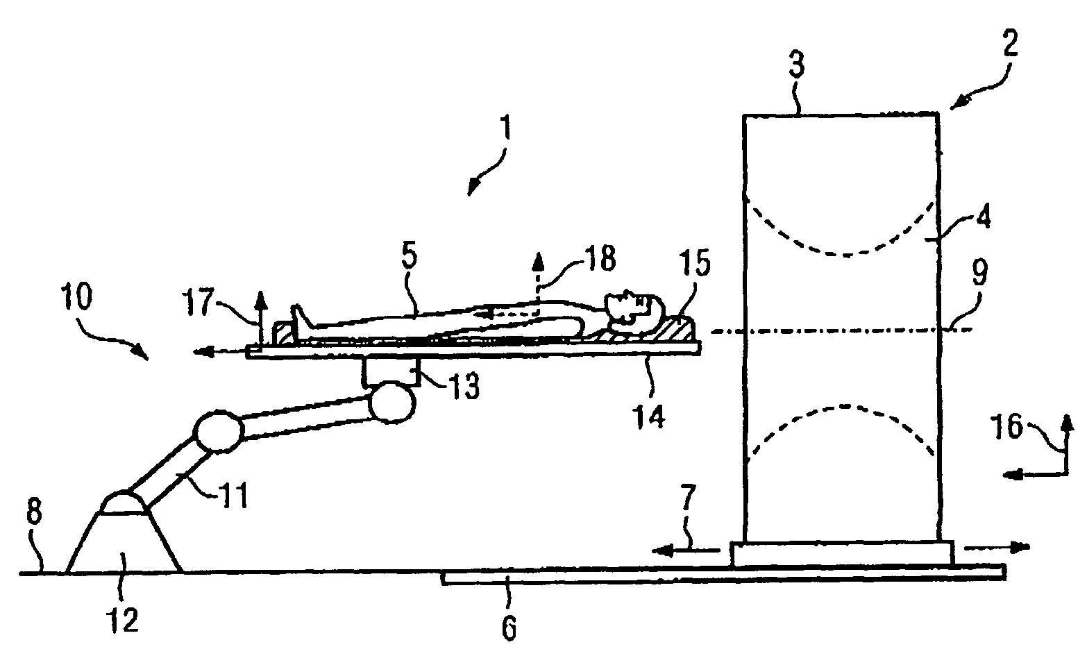
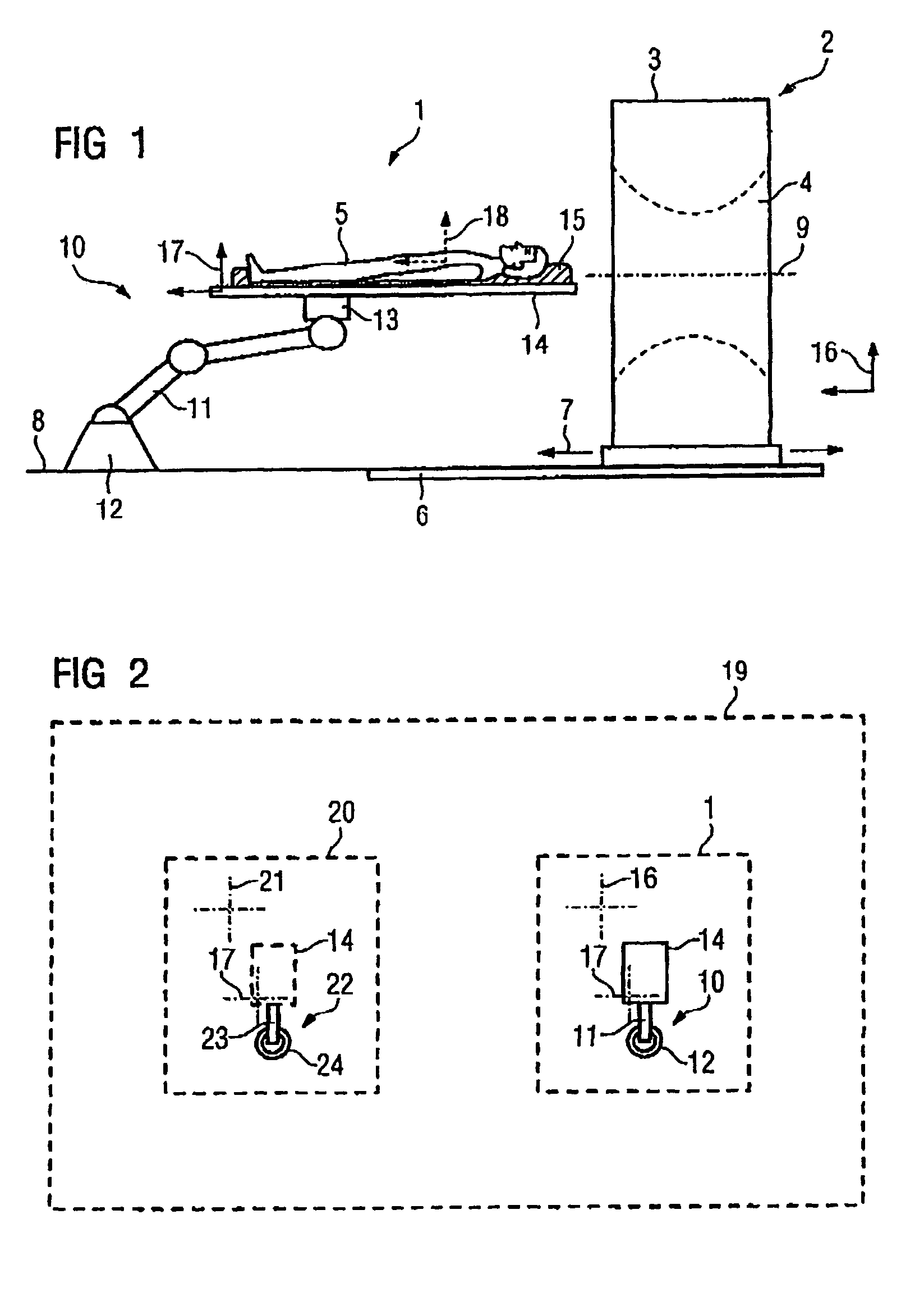
[0030]In one embodiment, as shown in FIG. 1, an imaging device 1 includes a computed tomography system 2 (“CT”) as its image-making unit. The CT 2 includes a CT gantry 3 with a tunnel 4 into which a patient 5 is pushed during a CT examination. The CT gantry 2 is disposed and fixed displaceably on a rail system 6 in a displacement direction 7 on the floor 8 of an imaging space. The displacement direction 7 is oriented horizontally and is parallel to an isocentric axis 9 of the CT gantry 3. The patient's 5 body longitudinal axis is oriented along or parallel to the isocentric axis 9. Alternatively, the patient 5 is supported in inclined (i.e. perpendicular) fashion to the isocentric axis 9.

[0031]In another embodiment, the imaging device 1 includes a table 10 that supports and positions the patient 5 in the examination position. The table 10 includes a support arm 11, which is embodied as either a manually adjustable support arm or as a robot arm, and has one end fixed on the floor 8 i...


PUM


Abstract

An imaging device and therapy facility are provided. An imaging device includes a table that supports a patient. An image-making unit is operative to create digital picture data of a body region of the patient. The image-making unit is operative to three-dimensionally scale the coordinates of the picture data recorded with respect to a space coordinate system that is stationary with the table, with respect to a table coordinate system that is stationary with a patient support of the table, or with respect to both the space coordinate system and the table coordinate system.

Description

[0001]The present patent document claims the benefit of the filing date of DE 10 2005 053 488.0, filed Nov. 9, 2005, which is hereby incorporated by reference.BACKGROUND[0002]1. Field[0003]The present embodiments relate to an imaging device and a therapy facility having an imaging device.[0004]2. Related Art[0005]Three-dimensional picture data of the patient's body are typically used when planning for medical therapy, for example, in the field of radiation therapy. Before the actual therapy session, the body region to be treated, such as a tumor, is located as exactly as possible using the three-dimensional picture data. The picture data are typically recorded in an imaging step that precedes each treatment session so as to detect any spatial change in this body region compared to earlier treatments, for example, a change in size or shifting of a tumor in the body tissue.[0006]Conventional medical imaging processes are used to generate the set of three-dimensional picture data. Exam...

Claims


Application Information

Patent Timeline
Patent Type & Authority Patents(United States)
IPC IPC(8): A61N5/10
CPCA61B6/04A61B6/4429A61B6/466A61B6/547A61B5/0555A61B6/032A61B6/0421A61B6/4405A61N2005/1061A61B5/055A61B5/704A61B5/702
Inventor RIETZEL, EIKESOMMER, ANDRES
Owner VARIAN MEDICAL SYST PARTICLE THERAPY GMBH & CO KG
Why Eureka
Try Eureka