Process and system of energy signal detection

a technology of energy signal and processing system, applied in the field of energy signal detection, can solve the problems of reducing the processing power reducing the sensitivity of older detecting processors, and loosing credibility of security industry with government and private enforcement agencies. , to achieve the effect of improving sensitivity, performance and reliability, and reducing false alarms

Active Publication Date: 2009-06-09
SYST GROUP
View PDF4 Cites 2 Cited by
  • Summary
  • Abstract
  • Description
  • Claims
  • Application Information

AI Technical Summary

Benefits of technology

[0015]A main object of the present invention is to provide a process and system of energy signal detection that not only improves the sensitivity, performance and reliability thereof, but also reduces false alarms by distinguishing between noise and real signals.
[0018]Another object of the present invention is to provide a process and system of energy signal detection, which improves energy input resolution by providing a differential voltage reference internally for the inputted energy signals.
[0019]Another object of the present invention is to provide a process and system of energy signal detection, which further increases resolution by not taking any signal conversion as an accurate measurement of the signals but to sample all inputted energy signals with time for data processing.
[0021]Another object of the present invention is to provide a process and system of energy signal detection which can avoid false alarms created by white light without the use of complicated and expensive lens that is made to block the white light or the installation of a white light filter on the lens or the sensor or a white light detector, such as CDS photocell detector.
[0022]Another object of the present invention is to provide a process and system of energy signal detection which can substantially achieve the above objects while minimizing the mechanical and electrical components so as to minimize the manufacturing cost as well as the ultimate selling price of the system.

Problems solved by technology

The great number of false alarms is causing the security industry to loose credibility with government and private enforcement agencies.
A drawback of the traditional energy signal detector is the filter and gain stages.
Older detecting processors do not have the processing power for more elegant techniques to be used.
Higher end, more expensive, energy signal detectors can include a secondary sensing method (such as a micro wave sensor) where it needs one technology to confirm the other in the decision making process.
A major problem for the conventional energy signal detector, especially a motion detector, is that the output signal of the pyroelectric sensing module (+DC offset) is very low, typically in the order of milli-volts, so that the output signal corresponding with actual physical movement within the detecting area is easily superseded by surrounding noise or other factors which may affect the infrared energy received by the pyroelectric sensing module.
As a result, the overall performance of the conventional motion sensor will be limited.
A persistent problem with such signal filtering and signal amplifying strategies is that some signals which reflect the actual physical movement, as opposed to surrounding noise, may be mistakenly removed by the signal filtering circuitry so that the real or actual physical movements within the detecting area may not be successfully detected.
On the other hand, those output signals which reflect surrounding noise or any other environmental factors may be mistakenly interpreted as an actual physical movement in the detecting area so that false alarms may be generated as a result.
Aside from significant cost increases with this approach, it still has its technical drawbacks as well.
For example, the DSP consumes higher power than what is typically allotted for a PIR design.
The problem here is this signal exists predominantly in the time domain.
There is no consistent signal frequency to analyze.
Also the slower in frequency the signal is, the more storage and horsepower will be required by the processor to be able to detect it.
This then becomes as issue for storage of the samples to be worked on.
Increasing the storage, results in increasing the cost yet again.

Method used


Image

  • Process and system of energy signal detection
  • Process and system of energy signal detection
  • Process and system of energy signal detection

Examples


Embodiment Construction

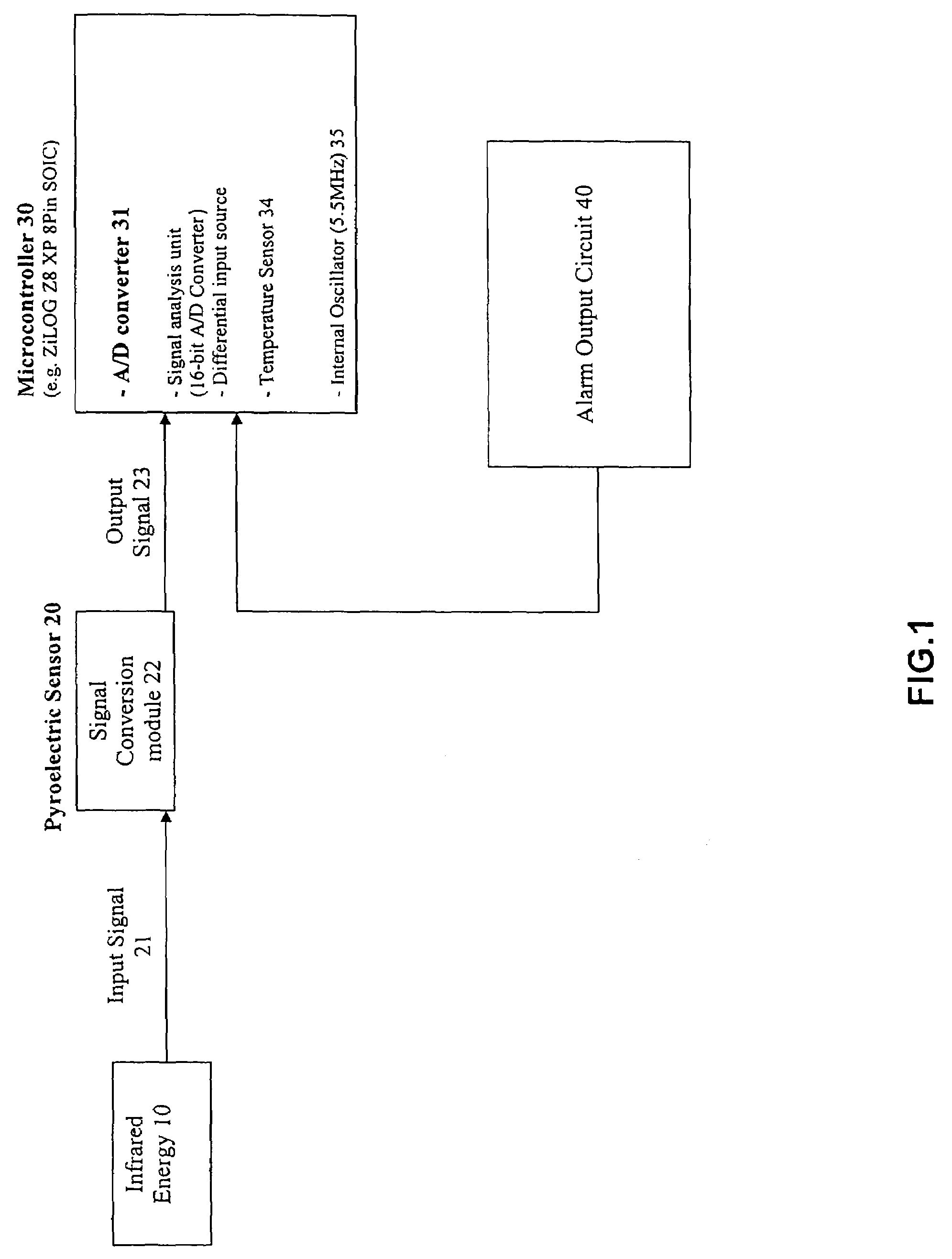
[0052]Referring to FIG. 1 to FIG. 4 of the drawings, the present invention provides a process and system of energy signal detection according to a preferred embodiment as illustrated. The process and system of energy signal detection according to the present invention is adapted to detect motion, such as a PIR motion detector, or various other kinds of energy derived from sensors for items such as smoke, temperature, gas, and light.

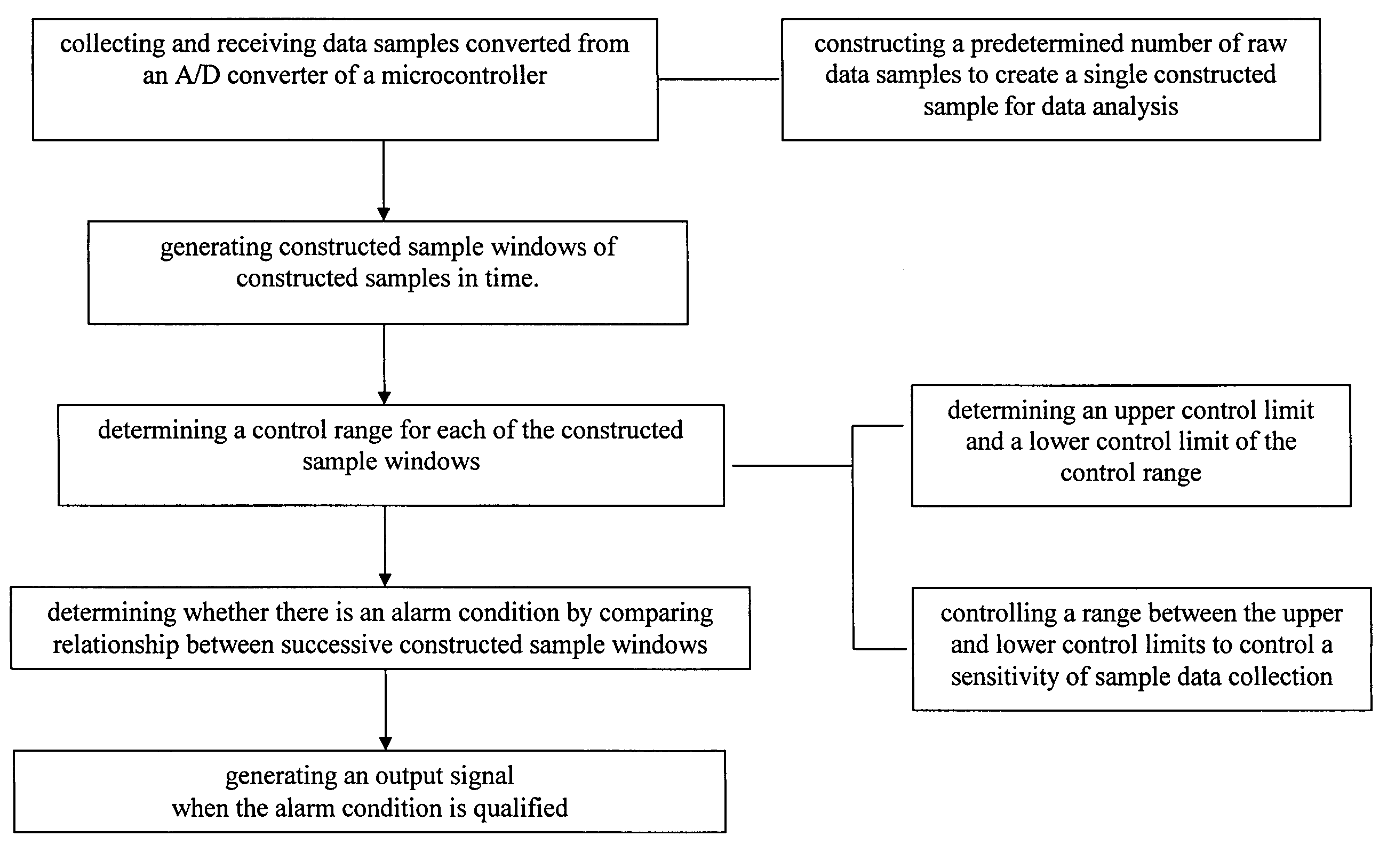
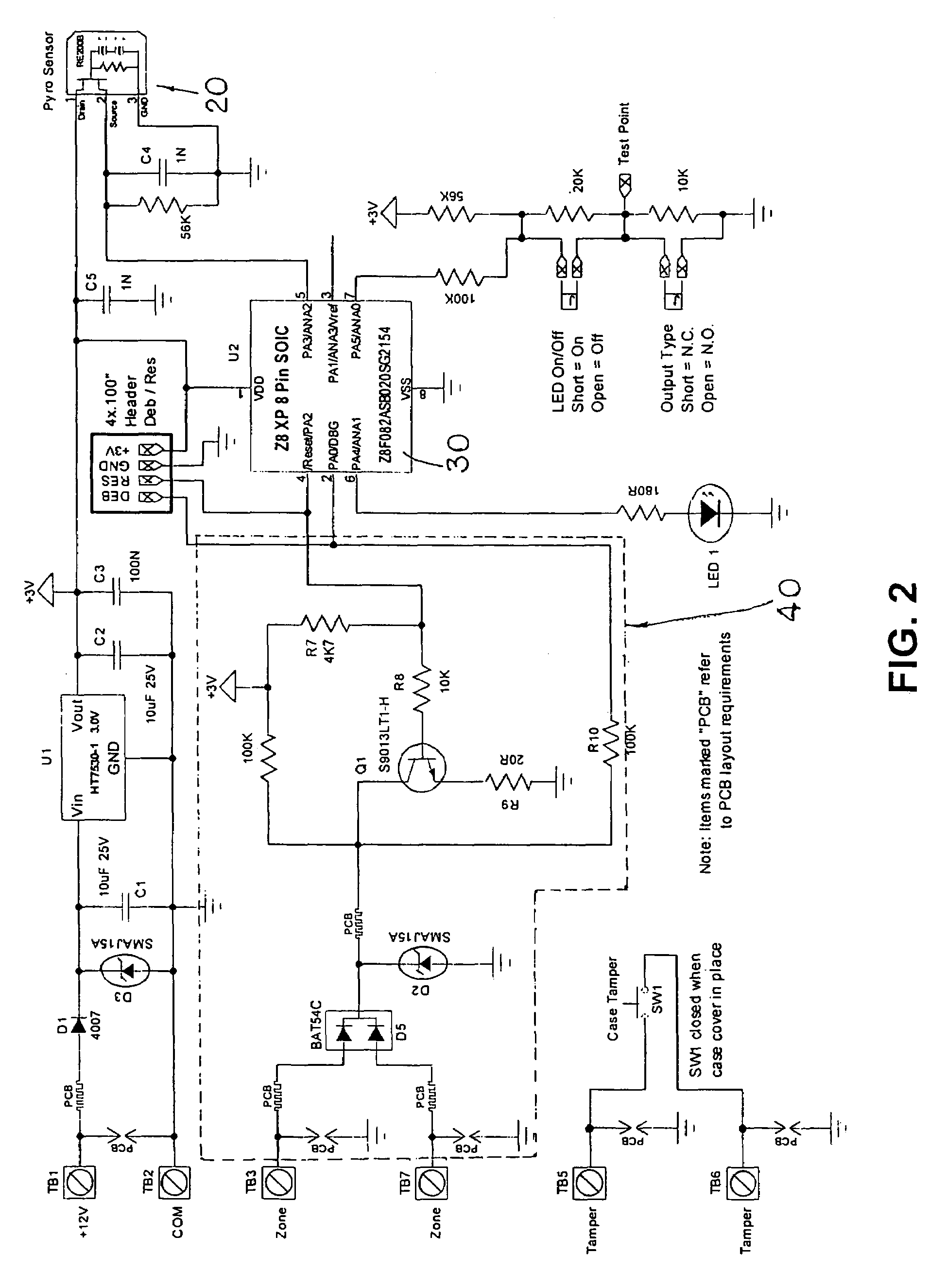
[0053]According to the present invention, the system of energy signal detection comprises an energy sensor 20, a microcontroller 30 and an alarm output circuit 40, wherein the energy sensor 20 is adapted for defining a detecting area and detecting energy directed there within to produce inputted energy signals.

[0054]The microcontroller 30, which is electrically connected to the energy sensor 20, comprising an analog-to-digital converter (A / D converter or ADC) 31 to convert the inputted energy signals into data samples, wherein a plurality of data samples ...


PUM


Abstract

A process and system of energy signal detection, which improves sensitivity, performance and reliability thereof and reduces false alarms by distinguishing between noise and real signals, includes the steps of receiving a plurality of data samples and generating a predetermined number of constructed sample windows of constructed samples in time, determining a control range for each of said constructed sample windows, determining whether there is an alarm pre-condition by comparing relationship between successive constructed sample windows, and generating an output signal when the alarm pre-condition is qualified.

Description

BACKGROUND OF THE PRESENT INVENTION[0001]1. Field of Invention[0002]The present invention relates to energy signal detection, and more particularly to a process and system of energy signal detection that can minimizes false alarms and maximize the sensitivity, performance and reliability of the energy signal detection.[0003]2. Description of Related Arts[0004]The great number of false alarms is causing the security industry to loose credibility with government and private enforcement agencies. A trend of no response policies and heavy fines for false alarms is in place already for many jurisdictions. Some false alarms are user related, but the majority of false alarms originate from Passive Infra Red (PIR) detectors, most of which in use today are low end, low cost units.[0005]A motion detector is a kind of energy signal detection device which utilizes Passive Infra-Red (PIR) technology to detect movement of body heat to activate the alarm in the event of an intrusion. The conventio...

Claims


Application Information

Patent Timeline
Patent Type & Authority Patents(United States)
IPC IPC(8): G06F19/00G06F17/40
CPCG08B13/19G08B29/185
Inventor PARKER, JAMESWANG, RANDALL
Owner SYST GROUP
Why Eureka
Try Eureka